Custom PWC hull shaping adjusts planing surfaces, deadrise, chine geometry, pads, strakes, and steps to trade stability, lift, drag, and turn bite for a specific performance target. When your craft is power-limited or has a severe center-of-gravity constraint, reshaping the hull rarely moves the needle. But when you’re chasing race top-speed, eliminating porpoising, improving corner bite in rough water, or tailoring handling to a specific water state, geometry changes to the running surface are the highest-leverage tool available.
The primary features a shaper will alter, and what each controls:
- Deadrise angle: Ride comfort, roll damping, and rough-water capability
- Pad width and shape: Top-speed drag, planing lift, and hump transition behavior
- Chine geometry (hard vs. soft): Cornering bite, spray deflection, and roll resistance
- Strakes: Lateral tracking, lift distribution, and spray management
- Steps: Wetted surface reduction at speed, trim angle, and directional stability
- Tunnel/keel geometry near intake: Boundary-layer control into the pump and top-speed efficiency
- Sponsons: Roll damping and turn entry behavior
The technical vocabulary used throughout this article draws on Savitsky planing analysis, parametric CAD workflows using NURBS/B-splines, computational fluid dynamics (CFD), and controlled sea-trial protocols. Each of those tools is covered in its own section below.
Key Takeaways
Custom PWC hull shaping delivers measurable performance gains when the geometry change is matched to a specific, instrumented performance gap and validated through controlled sea trials before any permanent modification is made.
| Point |
Details |
| When shaping helps |
Hull geometry changes deliver gains for top speed, porpoising, corner bite, and rough-water handling when tuning hardware is already optimized. |
| Highest-impact geometry knobs |
Deadrise, pad width, strake position, step placement, and intake keel radius each control distinct performance metrics with predictable trade-offs. |
| Testing-first workflow |
Baseline all metrics with GPS, RPM, trim sensor, and IMU before fabrication; change one variable per test session and compare against baseline data. |
| Main risks to avoid |
Poor fairing quality, asymmetrical changes without verification, skipping sea-trial instrumentation, and ignoring CG shifts from added material. |
| IPD Racing tuning-first path |
IPD Racing’s ride plates, nozzle hardware, and handling parts are the reversible first step before committing to irreversible hull reshaping. |
Table of Contents
What does PWC custom hull shaping actually change?
Before cutting foam or laying glass, every tuner needs a shared technical vocabulary. The terms below are the ones builders and engineers use when discussing hull shaping for personal watercraft, and each maps directly to a measurable performance outcome.
Core geometry terms and how to measure them
Deadrise is the angle between the hull bottom and a horizontal plane, measured at any transverse station. A flat-bottomed hull has 0° deadrise; a deep-V runs 20–25° or more at the transom. According to The Watercraft Journal, deadrise above 24° improves rough-water capability but makes the craft feel tippy at rest and reduces low-speed stability. Measure deadrise with a digital angle gauge at the transom and at multiple stations forward.
Rocker is the longitudinal curvature of the keel from bow to stern. More rocker lifts the bow at rest, helps the craft pivot in turns, and reduces tendency to dig in at low speed. Less rocker flattens the running attitude and increases planing efficiency at high speed. Measure rocker by placing a straight edge along the keel and recording the gap at each station.
Planing surface (pad) is the flat or near-flat section of the hull bottom aft of the step or keel entry. Pad width and length directly set the planing lift area and the wetted surface at speed. A wider pad generates more lift but also more drag at lower speeds.
Chines are the longitudinal edges where the hull bottom meets the hull sides. A hard chine creates a sharp corner that deflects spray outward and provides a defined hydrodynamic edge for cornering. A soft chine rounds that transition, giving gentler handling but less bite in turns.
Strakes are longitudinal ridges or fins on the hull bottom. They distribute lift, channel water flow aft, and reduce spray. Their height, width, and fore-aft position each affect handling differently.
Steps are transverse breaks in the planing surface that introduce air under the hull aft of the step, reducing wetted surface at speed. Stepped hulls can be advantageous above roughly 45 knots, but placement must be precise to avoid ventilation and directional stability issues.
Tunnel/keel geometry refers to the shape of the hull bottom in the area leading to the pump intake. The radius of the drop-keel in this zone controls the boundary layer entering the pump, which directly affects thrust efficiency and top speed.
Beam and waterplane set the overall width and the area of the hull at the waterline. Wider beam increases initial stability but adds drag.
Transom trim angle is the angle of the transom relative to vertical. Combined with the ride plate and nozzle trim, it sets the running attitude and wetted length at speed.
| Term |
What it controls |
How it’s adjusted in custom shaping |
| Deadrise |
Roll damping, ride comfort, rough-water behavior |
Foam fairing to increase locally; grinding/reshaping to reduce |
| Pad width/length |
Planing lift, top-speed drag, hump transition |
Adding foam/glass pad extensions or trimming existing pad |
| Chine geometry |
Cornering bite, spray deflection |
Reshaping chine radius with fairing compound or new glass layup |
| Strakes |
Lift distribution, lateral tracking, spray |
Adding or re-profiling with foam and biaxial fiberglass |
| Steps |
Wetted surface at speed, trim angle |
CNC-cut plugs, mold work, or direct glass freeforming |
| Tunnel/keel radius |
Boundary-layer control into pump |
Foam fairing and epoxy glass near intake |
| Rocker |
Bow lift, turn pivot, planing efficiency |
Difficult to change without full hull panel; usually addressed via ride plate |
| Sponsons |
Roll damping, turn entry |
Bolt-on or bonded additions; adjustable on some platforms |
Each geometry change produces a predictable hydrodynamic response. The table below maps the most common custom-shaping moves to their expected outcomes and primary trade-offs. Understanding these relationships is what separates a targeted modification from a guess.
Deadrise is the most fundamental lever. Increasing deadrise at the transom softens the ride in chop and adds roll damping, but it reduces the planing lift area and raises drag at a given speed. Riders feel this as a more planted, comfortable ride that requires slightly more throttle to reach the same top speed.
Pad width controls how much flat surface is in contact with the water at planing speed. A wider pad generates more lift, which reduces trim angle and helps the craft plane earlier. The trade-off is higher drag at lower speeds and reduced maneuverability in tight turns. Narrowing the pad reduces drag at top speed but makes the hump transition more demanding.
Strakes add lift and lateral resistance. Taller, wider strakes improve tracking and reduce spray but increase drag. Repositioning strakes forward shifts the center of pressure forward, which can reduce porpoising. Moving them aft increases stern lift and can help with hump transition.
Steps are the highest-risk, highest-reward modification. A correctly placed step reduces wetted surface at speed, which lowers frictional drag and can meaningfully increase top speed. Research on stepped hulls confirms they can be advantageous above roughly 45 knots, but the design requires careful longitudinal placement to avoid ventilation, asymmetrical suction, and reduced directional stability. Riders feel a stepped hull as a lighter, faster ride at speed with noticeably less drag, but a poorly placed step can cause sudden directional changes under load.
Bulging faces near the stern outside portion of the hull bottom generate a local negative pressure region during planing. This lifts the bow, increases trim angle, and can reduce rolling at speed. The effect is sensitive to the exact geometry of the bulge, so small dimensional changes produce measurable differences in trim behavior.
Keel radius near the intake is often overlooked but consistently delivers measurable gains. Reshaping the drop-keel radius in front of the pump intake controls the boundary layer entering the pump, which affects thrust efficiency and top speed without touching the rest of the running surface.
| Feature |
Typical change |
Expected performance delta |
Primary trade-off |
| Increase deadrise |
Add foam fairing to hull bottom |
Better roll damping, softer ride in chop |
Reduced planing lift, slightly higher drag |
| Widen pad |
Extend pad with glass layup |
Earlier planing, lower trim angle |
Higher drag at lower speeds, reduced turn agility |
| Add/raise strakes |
Bond new strake profile |
Better tracking, reduced spray |
Added drag, possible over-correction in turns |
| Add step |
Mold or freeform transverse break |
Lower wetted surface at speed, higher top speed |
Ventilation risk, directional stability concerns |
| Reshape bulging face |
Fairing compound or glass buildup |
Improved trim angle, reduced roll at speed |
Sensitive to geometry; small errors have large effects |
| Reshape intake keel radius |
Foam fairing near pump |
Better pump efficiency, top-speed gain |
Requires precise fairing; poor work worsens intake flow |
| Soften chine |
Fairing radius on chine edge |
Gentler handling, less spray |
Reduced cornering bite |
What fabrication methods do builders actually use?
Custom hull shaping in practice comes down to a handful of fabrication approaches. Each has a different cost, turnaround time, and level of reversibility. Choosing the right method depends on your performance target, budget, and whether you want to prototype first or go straight to a permanent modification.
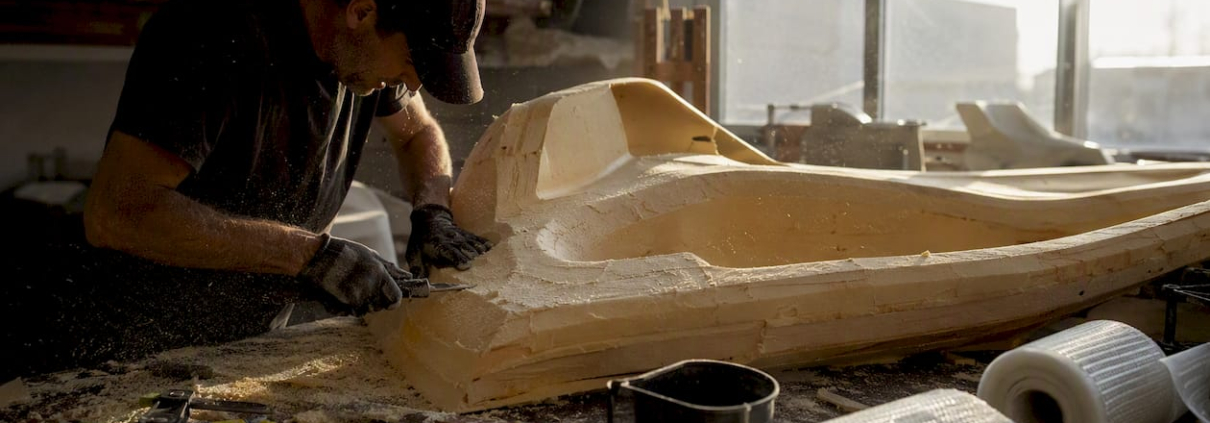
Foam fairing with fiberglass
The most accessible and reversible method starts with 2 lb/cu.ft. polyurethane foam blocks sculpted to the desired running surface profile. The foam is then covered with epoxy-saturated biaxial fiberglass and finished with gelcoat. Boatdesign consistently recommend this approach for trying new strake configurations and refining pump-intake radii before committing to permanent molds. The foam can be removed if the modification doesn’t perform as expected, making it the standard first step for any serious prototype work.
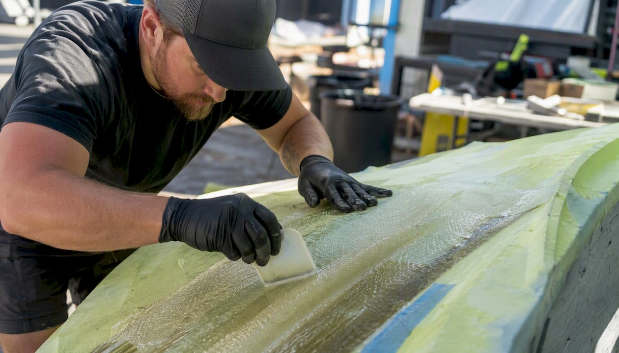
Materials needed: 2 lb/cu.ft. polyurethane foam, epoxy resin system (low-viscosity infusion or laminating grade), biaxial fiberglass cloth (typically 1708 or similar), peel ply, fairing compound, and gelcoat for finish.
Where hull panels are developable (meaning they can be unrolled flat without distortion), fiberglass freeforming lets builders produce very smooth molds without building a large plug first. This saves significant time and plug cost. The method requires careful fairing at joins and works best when the geometry change is modest and the surface is well-understood. For more complex three-dimensional shapes, a full plug is still the more reliable path.
CNC-cut plugs and molds
For production-quality modifications or when multiple identical hulls need the same change, CNC machining a foam or tooling-board plug from a CAD file is the most precise option. The plug is then used to pull a fiberglass mold, and the mold produces finished parts. CNC work adds cost and lead time but eliminates the dimensional uncertainty of hand-shaping. This approach makes sense when the parametric CAD work is already done and the modification is validated.
3D printing for plugs and pattern work
3D printing is increasingly used for small plugs, strake profiles, and pattern work where the geometry is complex and the part is small enough to print in sections. Print resolution and material selection matter: ABS or ASA for heat resistance, with post-print sanding and sealing before using as a mold surface. For full hull panels, 3D printing is still impractical at most shop scales, but for strake profiles and intake-area details it can save hours of hand-shaping.
Structural notes
Any modification that adds material to the hull bottom must account for the structural loads in that area. High-stress zones include the area around the pump intake, the transom corners, and the chine edges at the stern. Biaxial fiberglass over foam provides adequate stiffness for most fairing work, but areas subject to impact loading benefit from a Kevlar or foam-core sandwich layup. Resin cure must be complete before water testing: incomplete cure leads to delamination under hydrodynamic load.
Pro Tip: The single biggest differentiator between professional and amateur hull work is fairing quality. A perfectly faired running surface outperforms a geometrically correct but poorly finished one every time. Budget at least as much time for fairing and finish as for the structural layup itself.
How do you design and validate a hull modification before building it?
A repeatable design workflow prevents expensive mistakes. The process moves from objective definition through parametric modeling, preliminary empirical estimates, optional CFD analysis, prototype fabrication, and controlled sea trials.
Step-by-step design workflow
1. Define objectives. State the specific performance target: top speed at a given RPM, trim angle at speed, lap time on a known course, or handling behavior in a specific wave state. Vague objectives produce vague results.
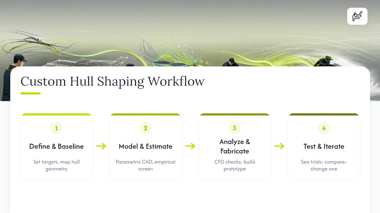
2. Baseline measurement and mapping. Document the current hull geometry at every station: deadrise, pad dimensions, chine profile, strake positions, and keel radius near the intake. Photograph the running surface dry and wet. Record current performance metrics using GPS, RPM logging, and trim sensor data.
3. Parametric modeling. Use a NURBS/B-spline CAD environment such as Rhinoceros with Grasshopper to build a parametric model of the hull. Modern parametric CAD workflows let designers modify hull features via sliders while maintaining geometric continuity and fair surfaces. For planing hulls specifically, longitudinal functions for deadrise distribution and tangent angles at stations provide a practical method to independently control features like deadrise distribution and chine geometry. Maintaining G1/G2 geometric continuity between feature curves keeps surfaces fair and manufacturable.
4. Preliminary empirical estimates. Before running CFD, use empirical resistance formulas to screen candidate geometries. The Keuning and Katgert method and the ITTC friction formula provide quick resistance estimates for planing hulls at a fraction of the cost and time of a full CFD run. These are best used to eliminate clearly inferior options before investing in higher-fidelity analysis.
5. CFD or panel model analysis. CFD is most useful for understanding pressure distribution across the running surface, identifying ventilation risks on stepped hulls, and evaluating the intake-area keel geometry. It is not always necessary for modest modifications, but for step placement or complex bulging-face geometry, a panel model or RANS CFD run can prevent costly fabrication errors. Generative design tools with attribute-based modifiers and space-shrinking can rapidly narrow the viable design space before committing to a single geometry, reducing the number of CFD runs needed.
6. Fabricate prototype. Build the modification using foam fairing and biaxial fiberglass as described above. Do not skip the prototype stage for any irreversible modification.
7. Controlled sea trials. Run the standardized protocol described in the testing section below. Record all metrics. Compare against baseline.
8. Iterate. Change one geometric variable at a time. Run the protocol again. Repeat until the performance target is met or the trade-off analysis shows diminishing returns.
CFD vs. empirical: when to use each
CFD is the right tool when you need pressure distribution data, want to evaluate ventilation risk on a stepped surface, or are optimizing a complex three-dimensional feature like the intake keel radius. It requires CAD geometry, solver setup time, and interpretation skill. Empirical methods (Keuning and Katgert, ITTC friction) are faster and cheaper for screening candidate geometries in early design stages. For most DIY or small-shop hull modifications, empirical screening followed by physical prototyping and sea trials is the practical workflow. CFD becomes worth the investment when the modification is complex, the performance target is tight, or the risk of a failed fabrication run is high.
| Metric to record |
Instrument |
Notes |
| Ground speed |
GPS (1 Hz minimum) |
Use dual-antenna GPS for heading accuracy |
| RPM |
Engine data logger or tachometer |
Log continuously during runs |
| Trim angle |
Trim sensor or IMU pitch channel |
Record at steady state and during acceleration |
| Roll angle |
IMU roll channel |
Critical for evaluating deadrise and sponson changes |
| Lateral acceleration |
IMU lateral G channel |
Use for cornering run analysis |
| Wetted surface |
Onboard camera (stern-facing) or laser scan |
Compare pre- and post-modification photos at same speed |
| Lap time |
GPS track with time sync |
Use for overall performance comparison |
| Subjective rider notes |
Voice recorder or synchronized video |
Time-stamp to data log for correlation |
What risks and trade-offs should you plan for?
Hull modification carries structural, handling, and operational risks that must be planned for before the first cut.
Structural risks
Improper fairing thickness is the most common structural failure mode. Too thin a glass layup over foam lacks the stiffness to resist hydrodynamic loading and will delaminate at speed. Too thick adds weight and can shift the center of gravity. High-stress areas, particularly the transom corners, the chine edges at the stern, and the pump intake surround, need additional reinforcement beyond the standard biaxial layup. Resin systems must be fully cured before water exposure: partial cure leads to hydrolysis and delamination over time. Fairing quality is not just cosmetic; builders consistently identify it as the critical differentiator between professional-grade modifications and work that fails prematurely.
Handling trade-offs
Increasing deadrise improves rough-water ride and roll damping but reduces low-speed stability. A hull with deadrise above 24° feels noticeably tippy at rest and requires more rider input to hold a straight line at low speed. Steps introduce ventilation risk: if the step geometry allows air to enter asymmetrically, the result can be a sudden, unexpected directional change at speed. Altered center-of-pressure from pad or strake changes can increase spin tendency in tight turns. Every geometry change shifts multiple handling characteristics simultaneously, which is why the one-change-at-a-time protocol is non-negotiable.
Operational risks
Any structural modification to the hull will void the manufacturer’s warranty on affected components. Resale value typically decreases for modified hulls unless the modification is documented, reversible, and the work quality is demonstrably professional. Before modifying a certified craft, confirm that the changes comply with applicable U.S. Coast Guard regulations and any class rules for the racing series you compete in. A single-sentence reminder: consult your local boating authority and class rules before making structural hull modifications to a registered watercraft.
Red-flag checklist
- Large asymmetrical geometry changes without CFD or physical symmetry verification
- No baseline performance data before starting
- Skipping the sea-trial plan and running modified hull without instrumentation
- Ignoring center-of-gravity shifts from added material weight
- Poor fairing work: visible ridges, air pockets, or incomplete glass coverage
- Changing multiple hull features between test runs
How do you run a custom hull-shaping project from start to finish?
A structured project plan prevents scope creep and ensures every modification is traceable to a performance outcome.
Pre-project documentation
Before any fabrication work begins, gather the following:
- Full photographic record of the hull bottom, dry and wet, at multiple angles
- Station lofting: measure and record deadrise, pad width, chine profile, and strake positions at every 6-inch station from transom to bow
- Hull scan (3D scan or manual offset table) if available
- Current CG and weight distribution (rider + fuel + gear)
- Baseline performance data: GPS top speed, trim angle at speed, lap time on a known course, and subjective handling notes
Numbered project checklist
- Define the performance objective in measurable terms (e.g., reduce trim angle at 55 mph by 2°, increase top speed by 3 mph, eliminate porpoising above 45 mph).
- Build or import the parametric CAD model of the current hull geometry using NURBS/B-splines.
- Run empirical resistance screening on candidate geometry changes using Keuning and Katgert or equivalent.
- Select the modification with the best predicted performance-to-risk ratio.
- Fabricate the mock-up using 2 lb/cu.ft. polyurethane foam shaped to the target profile.
- Apply biaxial fiberglass layup with epoxy resin; follow the manufacturer’s cure schedule fully.
- Fair the running surface to within 0.5 mm of the target profile; finish with gelcoat.
- Instrument the craft with GPS, RPM logger, trim sensor, and IMU before the first test run.
- Run the sea-trial protocol (described in the next section) and record all metrics.
- Compare results to baseline and objective. If the target is met, document the final geometry. If not, identify the single largest gap and plan the next iteration.
- Repeat steps 5–10 for each subsequent modification, changing one variable at a time.
- Finalize the modification with a permanent mold or CNC-cut part if the prototype performs as intended.
Timeline and cost estimates
DIY foam fairing and fiberglass work on a single hull feature typically runs 2–4 weeks elapsed time including cure windows, with material costs in the range of a few hundred dollars for foam, epoxy, and glass. A CNC-cut plug and pulled mold for a more complex modification adds significant cost and 4–8 weeks of lead time depending on shop availability. Full parametric CAD modeling by a naval architect or experienced hull designer adds professional fees that vary widely by scope. These are rough ranges; actual costs depend on hull size, modification complexity, and local shop rates.
Questions to ask your shaper or shop
- What experience do you have with stepped hulls or strake modifications on PWC platforms specifically?
- Can you provide instrumentation support for sea trials, or do I need to supply my own?
- Is this modification reversible, and what does reversal involve?
- What structural warranty do you offer on the layup and fairing work?
- Have you worked with the specific hull platform I’m running?
How do you test and tune after a hull change?
A standardized run protocol is the only way to know whether a modification worked. Without controlled testing, you’re comparing impressions, not data.
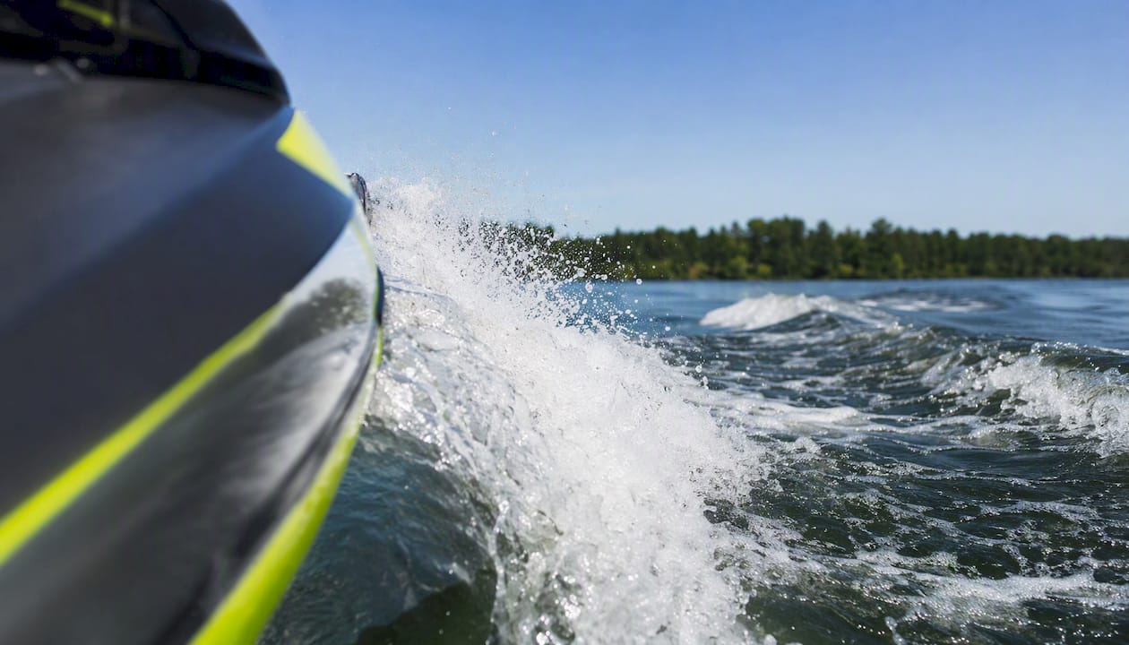
Standardized run protocol
Set environmental limits before each test session: wind under 10 mph, wave height under 6 inches, consistent water temperature. Use the same fuel load and rider weight for every run. Run each test condition a minimum of three times in alternating directions to cancel current and wind effects. Record steady-state runs at fixed speeds (typically 30, 40, 50, and maximum) and at least two full-throttle acceleration runs from a standing start. Include cornering runs at a fixed turn radius to evaluate roll damping and lateral G.
Instrumentation list
- GPS ground speed and heading: dual-antenna GPS at 5 Hz or better for accurate speed and track data
- RPM logger: continuous logging synchronized to GPS time
- Trim sensor: measures running trim angle at the transom
- IMU (inertial measurement unit): logs pitch, roll, and lateral acceleration at 50–100 Hz; critical for evaluating deadrise and sponson changes
- Onboard camera: stern-facing for wetted surface comparison, forward-facing for bow behavior
- Lap timer with GPS track: for overall performance comparison across sessions
What to log and how to analyze
Plot trim angle versus speed for each run and overlay the pre-modification baseline. A successful pad-widening modification should show a lower trim angle at a given speed. A successful step modification should show reduced wetted surface in the stern camera footage and lower RPM at the same speed. Lateral G traces from cornering runs reveal changes in roll damping and turn bite. Synchronize subjective rider notes to the data log using a voice recorder with a time stamp, then correlate rider feel to the objective measurements.
Iteration cadence
Change one geometric variable between test sessions. Run the full protocol. Evaluate the data against the baseline and the objective. Only then plan the next change. Changing multiple features between runs makes it impossible to attribute a performance change to a specific modification, which wastes both time and material.
Real-world outcomes: what do measured results look like?
Concrete case notes from shop and field experience illustrate how the methodology translates to measurable results.
Intake keel radius refinement
A common and high-return modification involves reshaping the drop-keel radius in front of the pump intake. In practice, builders who have refined this radius using foam fairing and epoxy biaxial glass report measurable improvements in top-speed and pump efficiency. The mechanism is straightforward: a smoother, more controlled radius reduces boundary-layer separation entering the pump, which improves thrust at high RPM. This modification is low-risk, reversible, and requires no CAD work for an experienced fabricator. It is consistently cited in builder forums as one of the highest return-on-effort modifications available on stock PWC platforms.
Strake repositioning for porpoising correction
Porpoising (rhythmic pitch oscillation at speed) is typically caused by a center-of-pressure that is too far aft relative to the center of gravity. Moving strakes forward shifts the center of pressure forward, which damps the oscillation. Builders who have made this change report that the porpoising is eliminated or significantly reduced, with no meaningful loss in top speed. The modification is straightforward with foam and glass, and it is fully reversible at the prototype stage.
Stepped hull for top-speed racing
For PWC offshore racing applications where top speed above 45 knots is the primary objective, a correctly placed step can reduce wetted surface and lower frictional drag. Builders who have added steps to racing hulls report that the craft feels lighter and faster at top speed, with a noticeable reduction in stern drag. The trade-off is a more demanding handling envelope: the craft requires more active rider input to maintain directional stability, particularly in turns. The step placement must be validated through sea trials, not assumed from the CAD model alone.
For deeper technical case studies and product-specific guidance, IPD Racing’s internal guides and product pages cover platform-specific modifications in detail.
The right priorities when planning a hull-shaping project
Most riders who come to hull shaping have already exhausted the obvious tuning options, or think they have. In practice, a significant number of performance gaps that look like hull problems are actually pump, nozzle, or ride-plate problems. Before committing to irreversible hull work, run through the full tuning checklist: ride plate selection, nozzle trim, impeller pitch, and intake grate configuration.
When the tuning options are genuinely exhausted and the performance data shows a clear hull geometry limitation, parametric CAD work is worth the investment if your performance target is tight and the modification is complex (steps, bulging faces, major deadrise changes). For simpler modifications (strake repositioning, intake keel radius, pad extension), direct shop prototyping with foam and glass is faster and cheaper than a full CAD workflow.
The one principle that holds across every project: instrument before you cut. Baseline data is the only reference point that tells you whether a modification worked. Without it, you’re tuning by feel, and feel is unreliable at the margins where hull shaping operates.
IPD Racing’s role in this space is straightforward: the parts catalog covers the tuning-first options that should precede any hull work, and the technical guides provide the engineering background to make informed decisions about when hull shaping is actually the right next step.
Before a hull modification makes sense, the data needs to show that tuning hardware has been fully optimized. IPD Racing stocks the performance parts that close most of the gap without touching the hull: ride plates, nozzle and trim hardware, impellers, and handling and control parts for Sea-Doo, Yamaha, Kawasaki, and other platforms. These are the lower-risk, reversible first steps that experienced racers and tuners run through before committing to foam and fiberglass.
For riders who have already worked through the tuning checklist and are ready for the next level, IPD Racing’s catalog includes hull and handling parts, strake hardware, and platform-specific upgrade kits. The Hot Products performance parts line covers engine, exhaust, and handling upgrades that complement hull work without requiring it. Browse the full catalog at IPD Racing and identify the parts that match your current performance gap before scheduling hull fabrication time.
Sources
The following sources provide the technical depth behind the methods covered in this article.
A parametric design method for planing hulls using longitudinal functions and shape coefficients (MDPI, 2025) — The primary reference for parametric planing-hull modeling using B-splines and longitudinal functions; directly applicable to deadrise distribution and chine geometry control.
Parametric ship hull definition using standard CAD tools (MDPI, 2023) — Covers NURBS/B-spline workflows in Rhinoceros and Grasshopper for maintaining fair surfaces during parametric modification; practical for any tuner building a CAD model of their hull.
IMDC 2022: Tool for parametric, generative, attributive and interactive modelling of yacht hull forms (Khan et al.) — Explains generative design with attribute-based modifiers and space-shrinking for rapid hull design exploration; also covers empirical resistance methods including Keuning and Katgert.
Massey University thesis on ground effect and stepped hulls — Detailed research on stepped-hull hydrodynamics, ventilation risks, and directional stability; essential reading before attempting any step modification.
Free Forming Fiberglass methods (BoatDesign.net PDF) — Practical fabrication guide for direct female molding and freeforming techniques; covers where the method works and where it requires additional care.
Modifying a PWC hull (BoatDesign.net forum thread) — Field-level builder discussion covering foam fairing materials, epoxy systems, biaxial glass selection, and intake-area keel radius work; the most practical starting point for DIY hull modification.
Know Your Hull: 9 Terms To Better Understand PWC Hull Design (The Watercraft Journal) — Accessible reference for core hull geometry terms with PWC-specific context; useful for confirming terminology before discussing modifications with a shop.
IPD Racing PWC tuning best practices — IPD Racing’s internal guide covering the tuning-first workflow and parts-focused alternatives that should precede hull reshaping decisions.
Recommended