Performance, Testing & How-To’s

Hands maintaining jet ski cooling system parts

Closed Loop Vs Open Loop: What Racers Need to Know

Closed-loop control uses sensors to measure output and correct it in real time; open-loop control fires off preset inputs and never checks the result. For most competitive PWC riders, closed-loop systems win on consistency across changing loads and water conditions, while open-loop setups win on simplicity and field repairability when something breaks mid-race weekend.

That trade-off shows up constantly on the dock:

  • Closed-loop cooling and throttle systems adapt to heat, load, and RPM shifts automatically.
  • Open-loop systems run on fixed settings that don’t adjust, but they also have fewer parts that can fail.
  • Sprint racers chasing repeatable lap times usually lean closed-loop; endurance and rough-water riders often prefer the open-loop margin for error.

Neither system is universally correct. The right call depends on your race format, your maintenance habits, and how much sensor failure you can tolerate on race day.

Key Takeaways

Closed-loop systems use sensor feedback to adapt to changing conditions, while open-loop systems run fixed inputs with fewer parts to fail, and the right choice depends on your race format and maintenance capacity.

Point Details
Feedback defines the split Closed-loop uses sensors to correct error; open-loop runs preset inputs with no correction.
Match system to race format Endurance racing favors closed-loop consistency; sprints and freestyle often favor open-loop simplicity.
Maintenance differs by architecture Open-loop needs flushing and screen checks; closed-loop needs coolant, ride plate, and sensor inspection.
Neither system fixes neglect Both still require pre-race checks, since sensor failure and clogged intakes cause similar downtime.
IPD Racing supports both paths IPD Racing stocks cooling, intake, and exhaust parts sized for closed-loop and open-loop PWC architectures.

Table of Contents

Closed Loop Vs Open Loop: Core Technical Differences

An open-loop system takes an input, runs it through a controller and actuator, and produces an output with no path back to check its work. A closed-loop system adds that path: a sensor reads the actual output, compares it to the target, and feeds the difference (the error) back to the controller so it can correct course. Wikipedia’s entry on closed-loop control frames this simply: feedback is the defining feature, and its absence is what makes a system open-loop by definition.

Three engineering concepts determine how well a closed-loop system performs once feedback enters the picture:

  1. Loop gain — how aggressively the controller reacts to error; too high and the system overshoots or oscillates.
  2. Bandwidth — how fast the system can respond to changing conditions, like a sudden load spike when you gun the throttle out of a turn.
  3. Phase margin — a stability buffer that keeps feedback from turning into runaway oscillation instead of correction.

Feedback interconnections change system dynamics in ways that aren’t always intuitive, which is why closed-loop design demands more careful tuning than open-loop design ever does.

On a PWC, this isn’t abstract. A closed-loop cooling system circulates coolant through a sealed loop and rejects heat through a ride-plate heat exchanger, keeping raw water away from the engine’s internal passages entirely. Open-loop cooling instead pulls raw water directly through the engine block and exhaust, which is simpler to build but leaves more metal exposed to whatever is in that water: silt, salt, weeds, or sand.

Statistic callout: Open-loop systems remain simpler, cheaper, and less dependent on sensors, while closed-loop systems trade that simplicity for better disturbance rejection and adaptability — the core engineering trade-off underneath every cooling and throttle decision on a race-prepped hull.

What This Means for Your Lap Times and Reliability

Feedback changes how a machine behaves once conditions stop being ideal, and race conditions are rarely ideal. A closed-loop cooling or throttle system compensates automatically as water temperature climbs, load shifts mid-turn, or RPM spikes on a straightaway. That compensation is where repeatability comes from: run the same course twice under slightly different conditions, and a well-tuned closed-loop craft holds its numbers closer than an open-loop one will.

Open-loop systems earn their keep differently. With no sensors reporting back, there’s nothing to fail electronically at the worst possible moment. A raw-water cooling jacket either flows or it’s clogged. You can diagnose it by eye at the trailer, without a wiring harness or a diagnostic tool.

  • Closed-loop wins: long motos with rising engine temps, variable chop, or back-to-back heats where consistency matters more than raw simplicity.
  • Open-loop wins: short sprint formats, budget-conscious builds, and anywhere field service beats precision.
  • Both matter: a properly tuned closed-loop system can outperform open-loop in variable conditions, but it’s genuinely vulnerable if a sensor drops out mid-race.

Throttle response follows the same logic, and it’s worth studying separately if you’re chasing corner-exit acceleration; see how throttle response affects race outcomes for the deeper mechanics.

Pro Tip: Carry a spare temp sensor and connector in your pit bag if you’re running closed-loop cooling. A $30 part failing mid-heat can cost you the whole moto if you don’t have a backup on hand.

How To Choose Between Closed Loop And Open Loop Setups

Picking a system isn’t about which is “better” in the abstract. It’s about matching the architecture to how and where you race.

  1. Check your race format first. Sprint racing under 10 minutes rarely stresses a cooling system enough to need closed-loop precision; endurance formats over 45 minutes almost always do.
  2. Assess your maintenance capacity. If you or your crew can’t troubleshoot sensors and wiring between heats, open-loop’s mechanical simplicity is the safer bet.
  3. Factor in your water conditions. Saltwater and silty coastal venues chew through raw-water passages faster, which pushes the case toward closed-loop protection for engine internals.
  4. Confirm aftermarket support exists for whichever architecture your hull runs, since parts availability determines how fast you get back on the water after a failure.
  5. Match it to your discipline. Freestyle riders cycling through short, high-load bursts often prioritize open-loop’s predictability over closed-loop’s adaptive range.

Before race day, ask your technician two questions: what sensors are on this craft, and what happens if one fails mid-heat? If they can’t answer both clearly, you have a gap to close before you line up. Riders dialing in tuning beyond cooling should also review PWC tuning best practices for racers before committing to a setup.

Maintenance Habits That Prevent Race-Day Failures

Open-loop and closed-loop systems fail differently, so they need different upkeep routines.

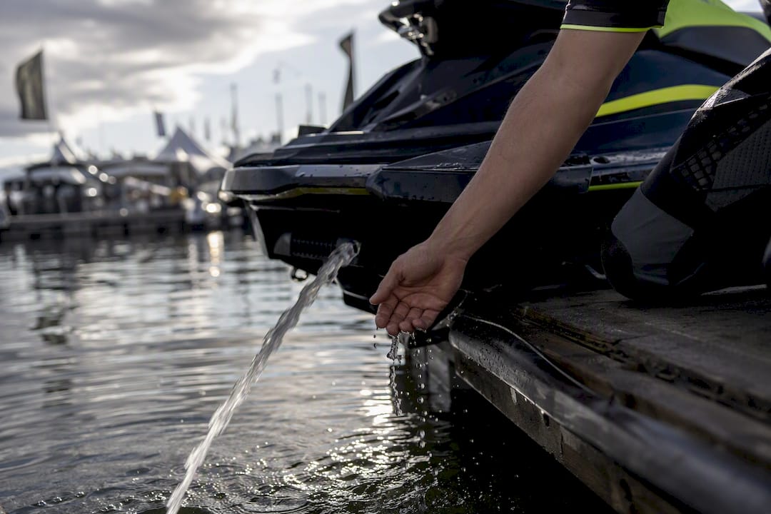
For open-loop cooling, flush the system with fresh water after every saltwater run, inspect the inlet screens and pisser stream for clogs, and check for corrosion where raw water contacts metal. Open-loop’s decades of reliable marine use come with a real cost: exposure to debris, corrosion, and dependence on ambient water temperature, so skipping a flush after saltwater is the single most common way riders shorten engine life.
Hand checking water flow from jet ski pisser stream

Closed-loop systems shift the maintenance burden rather than eliminating it. Check coolant condition and concentration each season, inspect the ride plate for dents or corrosion that reduce heat transfer, and test sensor connections and wiring for corrosion before every race weekend. Closed-loop cooling still relies on raw water flowing past the ride plate to reject heat, so running a craft out of water risks overheating regardless of which architecture you run. It also doesn’t remove raw water from every path. Exhaust and intercooler passages still contact it directly, so those still need a proper flush.

Pro Tip: Do a five-minute pre-race check on both systems: squeeze the pisser stream for flow, wiggle sensor connectors for corrosion, and look at the ride plate for fresh dents. Catching a problem at the trailer beats catching it at speed.

What IPD Racing’s Field Experience Tells Us About Cooling Choices

IPD Racing’s Jet Ski Cooling System Overview walks through both architectures at the component level, and that shop-tested guidance shapes how we recommend parts to racers prepping a craft for competition. When we evaluate a hull for race readiness, cooling architecture drives the checklist as much as horsepower does.

  • Ride plate condition gets checked first on closed-loop hulls, since a damaged plate cuts heat rejection before anything else does.
  • Impeller and intake grate condition matter on both architectures but carry more urgency on open-loop crafts, where debris has a direct path to the engine.
  • Exhaust cooling passages get flushed regardless of loop type, since raw water touches them either way.

A cooling system is only as reliable as its weakest inspected point, whether that’s a ride plate seal on a closed-loop hull or a debris-clogged intake grate on an open-loop one. Racers who treat cooling checks as part of race prep, not an afterthought, are the ones who finish heats instead of towing back to the trailer.

For riders running open architecture, we typically start with intake grates and impeller condition before touching anything downstream.

The Case Against Overthinking This Choice

Most of the advice floating around PWC forums treats closed-loop as the obvious upgrade and open-loop as the outdated fallback. That’s backwards for a lot of racers. The real question isn’t which system is more advanced. It’s which failure mode you’d rather manage on a Saturday morning with twenty minutes before your heat.
The Case Against Overthinking This Choice — overview diagram

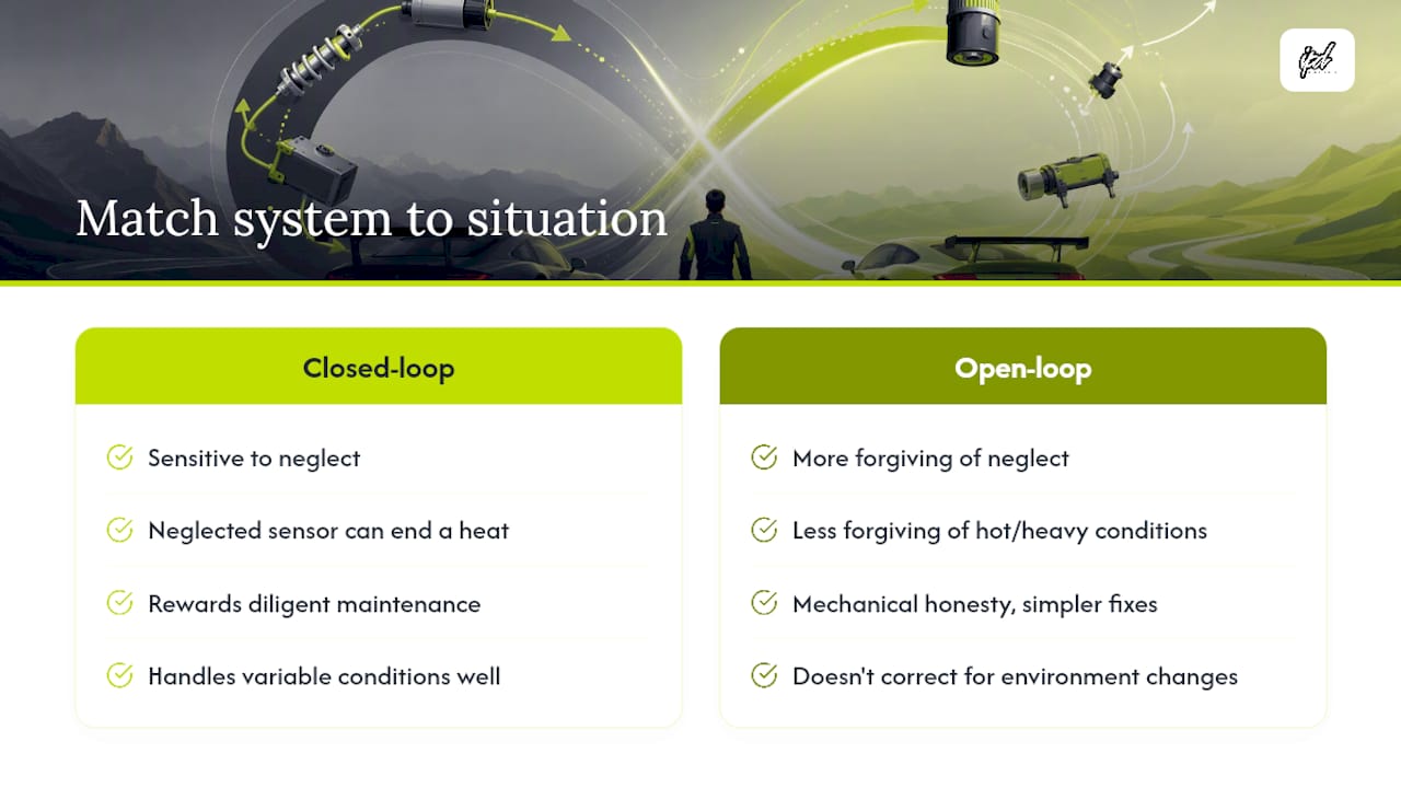
Closed-loop systems reward riders who maintain them properly and punish the ones who don’t. A neglected sensor or a low coolant level doesn’t just underperform, it can take you out of a heat entirely. Open-loop systems are more forgiving of neglect but less forgiving of variable conditions, since there’s nothing correcting for a hot day or a heavy load.

What actually matters is matching the architecture to your discipline and your willingness to maintain it. Endurance racers running long, hot motos gain real ground from closed-loop consistency. Sprint and freestyle riders often gain more from open-loop’s mechanical honesty. Neither choice is a shortcut around basic maintenance, and both punish riders who skip it.

— Casey

Get Race Ready With Parts Built For Either Cooling Architecture

Whichever system your hull runs, the parts behind it determine how well it holds up under race conditions. IPD Racing stocks cooling, intake, and exhaust components engineered for both closed-loop and open-loop setups, so you’re not guessing whether an aftermarket part fits your architecture.
IPD Racing

Start with the Jet Ski Cooling System Overview if you’re still mapping out which system your craft runs, then check the full parts catalog for ride plates, impellers, intake grates, and exhaust components sized for your platform. Racers dialing in exhaust behavior alongside cooling should also look at how electronically controlled exhaust systems respond to feedback, since valve-actuated exhaust follows the same control logic covered above. Browse the Hot Products lineup for current engine and PWC upgrades, and place your order before your next race weekend so parts arrive with time to install and test.

Sources

For readers who want the engineering behind this comparison, MathWorks explains open-loop and closed-loop mechanics in accessible terms, while Caltech’s feedback systems primer covers stability analysis in more depth. Aerotech’s breakdown of open versus closed-loop trade-offs applies directly to PWC hardware decisions, and Wikipedia’s closed-loop control entry offers a solid baseline definition for newer racers.

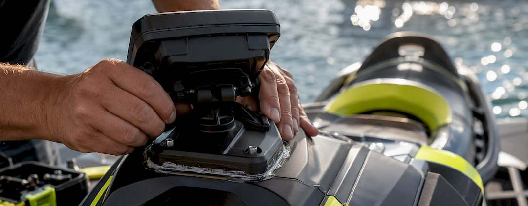
Hands installing rigid GPS mount on PWC cowling

The Right Way to Mount a GPS on Your PWC

The fastest, safest, and most reliable GPS install on a personal watercraft uses a rigid mount on the upper cowling, forward of the handlebars, secured with RAM-style backing hardware or an OEM mount kit, and powered through a plug-and-play pigtail connection. This location keeps the display in your natural line of sight, and a rigid mount resists the vibration that blurs screens and loosens hardware at speed. Sealing the mount base with marine sealant closes off the one entry point most flush installs get wrong.

Two alternatives work for specific riders. A glovebox bail mount suits smaller GPS units and riders who want minimal drilling, though it forces you to glance down instead of ahead. A waterproof phone mount on the handlebar center clamp works fine for casual riders running Navionics or Wavve Boating instead of a dedicated marine unit.

Whatever you choose, visibility and vibration resistance decide whether the install survives your first season on the water. Here’s the full pwc gps mount setup workflow, broken into every decision point that matters.

  • Primary approach: Upper cowling mount, RAM ball or OEM kit, pigtail power, marine sealant.
  • Alternative 1: Glovebox bail mount for compact units.
  • Alternative 2: Handlebar phone mount for app-based navigation.
  • Safety note: Never mount a unit where reaching it or reading it requires taking your eyes off the water for more than a glance.

Key Takeaways

A rigid upper-cowling GPS mount with pigtail power and marine sealant outperforms every other PWC mounting method for visibility, vibration resistance, and long-term reliability.

Point Details
Mount location matters most Upper cowling forward of the handlebars keeps the display visible without forcing you to look down.
RAM ball mounts resist vibration The ball-and-socket design absorbs shake that flat brackets transmit straight to the screen.
Pigtail power beats splicing Plug-and-play connections avoid damaging factory wiring and simplify future troubleshooting.
Sealant and gaskets prevent failure A tiny clearance error, even 1/16 of an inch, can compromise a seal or block a lid from closing.
Test under real riding posture Confirm the display is reachable and readable while holding your normal throttle stance, not just at the dock.

Table of Contents

Best Mounting Locations on a PWC

Where you put the GPS determines whether you actually use it. Riders who mount a unit somewhere awkward tend to stop checking it within a few outings, which defeats the purpose of installing one at all.

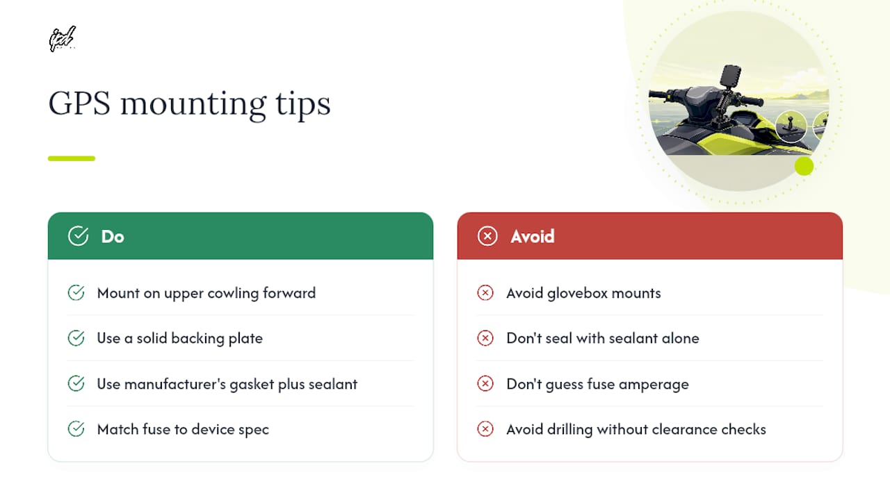
  1. Upper cowling or top deck, forward of the handlebars. This is the strongest all-around choice. It sits in your natural field of view, the cowling surface is usually flat enough for a solid base, and there’s typically enough clearance underneath for a backing plate. Before drilling anything, check clearance from underneath the cowling; even a small misjudgment on drill depth can hit wiring harnesses or structural ribs you didn’t know were there.
  2. Glovebox or storage-lid bail mounts. These need minimal drilling since many bail brackets clamp onto the lid’s lip rather than penetrating the surface. The trade-off is size: a bail mount only works with smaller displays, and you have to confirm the lid still closes and seals once the mount is in place. A mount that’s a hair too tall will prop the lid open just enough to let spray in.
  3. Handlebar mounts and center pad. Center-mounted units get more vibration than cowling mounts because the handlebar assembly moves independently from the hull in some designs. A stiff RAM arm minimizes flex, but expect more screen shake at speed than a top-deck install. Left-side handlebar placement is popular among riders who want the throttle hand free and the display close to their dominant eye line.
  4. Phone mounts versus dedicated marine units. A rugged waterproof phone mount running Navionics or Wavve Boating is cheaper and faster to install than a marine chartplotter, and it works on any of the best places to put a GPS on a jet ski that a dedicated unit would use. The catch is screen glare and battery drain in direct sun, which a purpose-built marine display largely avoids.

Pro Tip: Sit in your normal riding position before you commit to a location. A mount that looks perfect standing next to the ski often ends up blocked by your hands or torso once you’re actually leaning into a turn.

Mount Hardware: RAM Ball, Bail, Flush, and OEM Kits

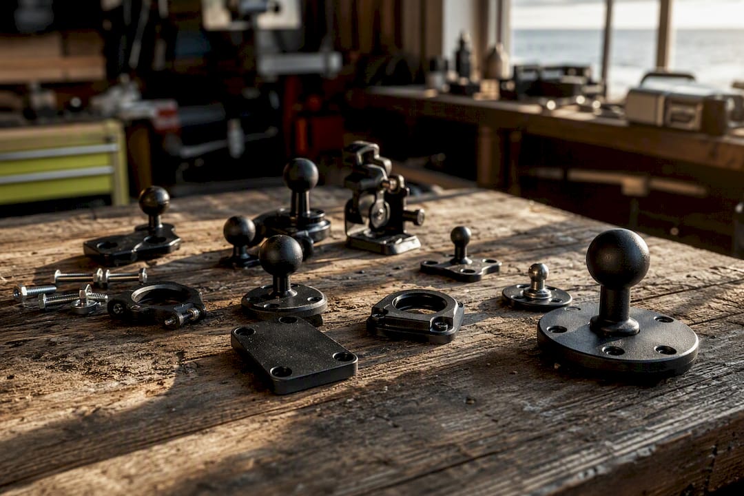
Close-up of assorted GPS mount hardware on bench

RAM ball mounts remain the go-to hardware for PWC GPS installs because the ball-and-socket design absorbs vibration instead of transmitting it straight into the device, and the socket arm gives you adjustment range you don’t get with a fixed bracket. Riders fitting the backing plate from underneath the cowling often get a tidy, rigid result when the hull structure allows access, according to one detailed Sea-Doo Spark forum install that walks through the process start to finish.

Which method fits depends on your hull and your device:

  • RAM ball mounts suit any location where you want adjustability and vibration damping, especially cowling and handlebar installs.
  • Bail or bracket mounts work best on glovebox lids and storage compartments where you want to avoid drilling through a sealed surface entirely.
  • Flush mounts give the cleanest look for dedicated chartplotters like a Garmin echoMAP, but they demand precise cutouts and full gasket sealing since the device sits recessed into the surface.
  • OEM mount kits, like the factory-style kit used on Sea-Doo Fish Pro models, come pre-matched to the hull’s mounting points and usually install in about an hour with basic tools, per a gallery install write-up from Watercraft Journal.

For thin cowlings, back the mount with a nut-plate instead of driving screws straight into gelcoat. Nut-plates spread the load across a wider area and cut down on the cracking that plagues single-screw installs on thin fiberglass. Use stainless steel fasteners throughout, since anything else corrodes fast in a saltwater environment, and apply anti-seize to threads before final torque so future removal doesn’t strip the plate.

Pro Tip: Countersink your screw holes slightly before mounting. A flush screw head sheds water instead of collecting it, which matters more than it sounds like on a surface that gets soaked every ride.

Wiring and Power: Pigtails, Fuses, and Routing

Whenever a plug-and-play pigtail is available for your GPS model, use it instead of splicing into factory wiring. Splicing factory audio or accessory circuits voids some warranty terms and creates a failure point that’s harder to diagnose later, especially once corrosion sets into a hand-taped connection. A factory-style kit for the Sea-Doo Fish Pro includes exactly this kind of pigtail as an add-on option, which keeps the entire wiring job plug-based rather than cut-and-splice.

  • Add an inline fuse close to the power source, sized to the device manufacturer’s spec, never to the wire gauge alone.
  • Route cable runs away from exhaust components and any moving parts like the steering cable or throttle linkage.
  • Secure the harness with zip ties every few inches so vibration doesn’t work it loose against a sharp edge.
  • Wrap any exposed connector in dielectric grease or a weatherproof cap before final assembly.
  • Leave a small service loop of slack near the connector so future maintenance doesn’t strain the wire.

Chafe is the quiet killer of PWC wiring installs. A harness that looks fine on install day can wear through its insulation after a season of engine vibration rubbing it against a metal bracket. Anchor points and foam sleeving at contact points cost almost nothing and prevent a much bigger repair down the line. IPD Racing’s PWC audio system upgrade guidance covers the same routing discipline for accessory wiring, and the principles carry over directly to GPS installs.

Pro Tip: Disconnect the battery before any wiring work, even for a pigtail plug. A brief short while your hands are near a live circuit is a bad way to learn why that step matters.

Mounting a Transducer for Fish-Finder Setups

PWCs present a real constraint for transducer placement: there’s no through-hull option on most hulls, so rideplate or stern-mount transducers are the practical path for owners adding fish-finding capability alongside GPS. A rideplate mount, bolted to the existing rideplate at the stern, keeps the transducer in clean water flow behind the jet pump rather than in turbulence, which matters for reading accuracy at speed.

  • Rideplate mounts give the cleanest signal because water flow across that section stays relatively undisturbed compared to areas closer to the hull’s chines.
  • External transom brackets work on some hull shapes but tend to introduce more cavitation noise into the reading at higher speeds, since the bracket itself disturbs flow before it reaches the sensor.
  • Cable routing from the transducer to the display has to clear the jet pump intake and any moving steering components entirely, with enough slack to avoid tension when the hull flexes.

Protect the cable run with a sleeve anywhere it passes near an edge or bracket, since the same chafe risk that threatens power wiring applies here, arguably more given how close the run sits to the pump housing. A transducer install that ignores hull flex around the intake area often shows intermittent dropout on the display, which reads as a device fault but is really a mechanical one. Riders focused on race-tuned hulls should weigh transducer drag against the tuning priorities that matter most for their setup, since any stern-mounted hardware adds a small amount of resistance.

Sealing the Install Against Water Ingress

Every flush or through-cowling install lives or dies on the seal. Garmin’s own install documentation for units like the echoMAP series calls for marine sealant between the mounting surface and the device housing, plus nut plates or backing plates on thin fiberglass sections where a screw alone won’t hold securely.

Even a small clearance miscalculation causes outsized problems: shop-level installers note that an error as small as 1/16 of an inch in drill placement can prevent a glovebox lid from closing fully or compromise the gasket seal around a flush-mounted unit, based on Wavve Boating’s install guidance. That’s a tolerance most home installers don’t think to check until the lid won’t shut right.

  • Clean and dry the mounting surface completely before applying sealant. Any residual wax or grime keeps the sealant from bonding.
  • Use the manufacturer’s gasket where one is supplied rather than sealant alone. The gasket is engineered for that exact cutout.
  • Countersink screw holes and use backing plates on thin gelcoat sections to avoid cracking under torque.
  • Apply dielectric grease to every connector before final assembly, and cap any unused ports with weatherproof plugs.
  • Recheck the seal after the first few rides. Sealant can shrink slightly as it cures fully.

The Complete Install Workflow, Step by Step

Follow this sequence and you avoid the two most common install failures: drilling before checking clearance, and wiring before confirming fuse protection.

  1. Pre-install verification. Confirm cowling clearance underneath your planned mount location, locate the nearest factory wiring harness, and hold the manufacturer’s mounting template against the surface to check fit before marking anything.
  2. Gather tools and parts. At minimum you need a drill with the manufacturer-specified bit size, a countersink bit, marine sealant, stainless fasteners, a multimeter, wire crimpers or a proper connector kit, and the mount hardware itself, whether RAM ball, bail bracket, or OEM kit.
  3. Disconnect the battery. Do this before any drilling or wiring begins, even if you’re only test-fitting.
  4. Drill and test-fit the backing plate. Start with a pilot hole, confirm alignment against the template, then drill to final size. Test-fit the plate and mount hardware before applying any sealant.
  5. Route and connect wiring. Use the plug-and-play pigtail where available, add the inline fuse near the power source, and secure the harness away from heat and moving parts.
  6. Seal the mount base. Apply marine sealant and the manufacturer’s gasket, then torque fasteners to spec, snug but not overtightened, since overtightening can crack thin fiberglass even with a backing plate installed.
  7. Reassemble and bench test. Reconnect the battery and power on the unit before you close up any covers, confirming the display, backlight, and GPS fix all work.
  8. Run a short sea test. Take it out at low speed first, then work up to a normal cruising speed to check for vibration blur, water intrusion, or connector issues.

Pro Tip: During your sea test, try reading the display while holding your normal riding posture under throttle, not just standing still at the dock. A unit that’s perfectly readable at idle can become unreadable once your hands, arms, and body shift into an actual riding position.

Testing and Fixing the Most Common Install Problems

A proper pre-ride check takes two minutes and saves you from discovering a problem twenty miles offshore. Confirm the unit powers on, gets a GPS fix within the expected time, and that the chart or map data displays clearly in direct sunlight. If you added a transducer, check for a consistent depth reading rather than intermittent dropout.

  • Blurry or shaking screen at speed almost always means the mount isn’t rigid enough. Swap a flexible bracket for a stiffer RAM arm or check that all mount fasteners are torqued to spec.
  • Water intrusion around a flush mount usually traces back to a seal that wasn’t fully cured before the first ride, or a gasket that shifted during installation. Reseal and let it cure the full time the manufacturer specifies before running the ski again.
  • Loose hardware after a few outings is a sign the backing plate wasn’t sized correctly for the surface, or fasteners weren’t using thread locker on a vibration-heavy mount point.
  • Intermittent transducer readings point to cavitation near the mount location or a cable run that’s picking up interference from nearby wiring; reroute the cable further from the harness first.

If you’ve checked all of the above and the issue persists, especially anything involving factory wiring harnesses, hand the job to a professional installer rather than risk damaging electronics you can’t easily replace.

What IPD Racing Sees in Real Shop Installs

Shop-level GPS installs succeed or fail on the same details every time: backing plates sized to spread load instead of concentrating it on one screw, anti-vibration hardware chosen over rigid-but-brittle brackets, and wiring harnesses routed well clear of heat sources and moving parts. These are the same principles behind IPD Racing’s engine mount upgrades and audio system installs, where vibration control determines whether hardware lasts one season or five.

  • Skip drilling until you’ve confirmed clearance from underneath the surface.
  • Choose nut-plates over direct screws into gelcoat wherever the cowling is thin.
  • Route every wire away from the exhaust and steering assembly before you zip-tie anything down.

Manuals, Tutorials, and Apps Worth Reviewing First

Before you pick up a drill, review the source material that matches your exact hardware. Manufacturer manuals carry the drill sizes and torque specs that generic advice can’t replace.

Why Most GPS Installs Fail Before They Start

The biggest obstacle to a good PWC GPS setup isn’t hardware. It’s hesitation. Riders buy a solid unit, then let it sit in a box because they’re unsure where to drill or how to wire it in without voiding a warranty. Forum threads on boards like Greenhulk back this up: mount uncertainty, not device quality, is what stalls most installs before they ever happen.

The conventional advice treats mounting as an afterthought to picking a GPS unit. That’s backward. Hardware choice matters far less than committing to one rigid, well-sealed location and executing it correctly the first time. A mid-range chartplotter on a bulletproof RAM mount beats a premium unit wobbling on a flimsy bracket every time you hit a wake at speed.

If you take one thing from this workflow, prioritize the mount’s rigidity and the seal’s integrity before you obsess over device features. Screen resolution won’t matter if the unit is unreadable at 40 miles per hour or dead from water intrusion by August. Get the mechanical foundation right first, then let the electronics do their job.

Frequently Asked Questions

What’s the best GPS mounting location on a jet ski?
The upper cowling forward of the handlebars is the strongest choice for most riders. It keeps the display in your natural line of sight and typically offers enough clearance underneath for a solid backing plate, unlike glovebox locations that force you to look down.

Do I need to drill into my PWC to install a GPS mount?
Not always. Bail or bracket mounts on a glovebox lid often require minimal or no drilling. A flush-mounted chartplotter or a cowling-mounted RAM ball system does require drilling, along with careful clearance checks beforehand.

Can I use a smartphone instead of a dedicated marine GPS?
Yes. A rugged waterproof phone mount paired with an app like Navionics or Wavve Boating is a cheaper, faster setup than a marine chartplotter, though screen glare and battery drain in direct sun are trade-offs worth considering.

How do I prevent water from getting into a flush-mounted GPS?
Use marine sealant along with the manufacturer’s gasket, never sealant alone, and confirm the mounting surface is completely clean and dry before applying either. Recheck the seal after your first few rides since sealant can shrink slightly as it cures.

What size fuse does a PWC GPS installation need?
Fuse size should match the device manufacturer’s power specification, not just the wire gauge you’re using. Check your GPS unit’s install documentation for the exact amperage rating before wiring in the inline fuse.

Frequently Asked Questions — overview diagram

Ready to upgrade your mounting hardware or source backing plates built for high-vibration installs? IPD Racing’s shop carries mounting accessories and fasteners designed for PWC-specific installs, and the ProWatercraft handling parts relaunch covers additional hardware worth pairing with your GPS setup.

Sources

  • Best GPS for Jet Ski | Top Devices & Smart Navigation Options – Wavve Boating
Jet ski nose rocker lifting during freestyle maneuver

Why Jet Ski Nose Rocker Matters for Freestyle Tricks

Nose rocker matters for freestyle because it increases the hull’s leverage to lift the bow and cuts the resistance a ski fights when rotating into a flip or barrel roll. More rocker means faster pop, quicker rotation initiation, and more forgiving airtime on aerial tricks. The trade-off is real: aggressive rocker sacrifices top speed and high-speed tracking, since less hull stays in contact with the water at a given trim angle.

  • More rocker: easier pop, faster rotation, better trick initiation
  • More rocker: less top speed, more sensitivity in rough water
  • Less rocker: flatter, faster, more stable, but harder to snap into rotation

At IPD Racing, Casey has spent years tuning hulls for riders chasing consistent flips instead of raw speed, and that field experience shapes every recommendation below.

Key Takeaways

Nose rocker increases nose lift and reduces rotation resistance, giving freestyle riders faster pop and easier flip initiation at the cost of top-speed stability.

Point Details
Rocker drives trick initiation More bow curve means less wetted surface and easier nose lift for pops and flips.
Trade-off is real Aggressive rocker reduces high-speed stability and top-end tracking.
Pair rocker with hull mods Transom chops and sponsons work together with rocker to keep the hull controllable.
Test incrementally Change one variable at a time and log rotation speed, pop height, and landing stability.
Match parts to your setup IPD Racing’s sponson and handling parts support each stage of the tuning sequence.

Table of Contents

How Nose Rocker Changes Pop, Rotation, and Wetted Surface

Rocker profile describes the curve of the hull bottom from bow to stern, measured as how much the nose lifts relative to a flat baseline. Wetted surface is simply how much of that hull bottom stays in contact with the water while you’re riding. The two are connected: increase the rocker curve, and you reduce wetted surface at the bow, which changes how the ski responds to throttle and body weight.

Think of the hull as a lever; for more details on how hull behavior affects performance in waves, see our explanation of yacht sea keeping ability. A pronounced rocker gives you more leverage to lift the nose because less bow surface is fighting water resistance. That’s why a more pronounced rocker increases maneuverability and pop for tricks, while flatter hull sections trade that agility for straight-line speed and stability. You feel this the moment you chop the throttle into a flip attempt: a high-rocker hull answers almost immediately, while a flat-bottomed recreational hull needs more input to break free.

  • Reduced wetted surface lowers drag but also reduces low-speed grip
  • Aggressive rocker can push more spray and air into the pump inlet during aerated white water
  • Cavitation risk rises when the intake grate sits shallower relative to the water surface after a rocker increase

That last point catches a lot of riders off guard. Increase rocker without adjusting intake positioning, and you can starve the pump of clean water mid-trick, right when you need consistent thrust to complete a rotation. IPD Racing’s guide on how PWC hull rocker affects performance breaks down that pump-timing relationship in more detail.

How Do Sponsons and Transom Length Interact With Rocker?

Nobody who rides freestyle seriously changes rocker in isolation. Rocker works as part of a system, and the hull mods around it decide whether that added lift turns into clean tricks or an unpredictable ride.

Shortening the transom, often called a rear chop, is the most common companion mod. Cutting 2 to 4 inches off the tail reduces the length of hull dragging behind the pivot point, which amplifies the nose-up tendency rocker already creates. Freestyle-specific hulls commonly run shorter than stock recreational skis specifically to pair with aggressive rocker profiles, and that combination is what lets lower-horsepower setups still pull off flips.

Sponsons and bondline shaping do the opposite job: they claw back the stability that rocker gives up. A wider bondline and tapered front sponsons help the hull hook into a wave face instead of skipping off it. One detailed rider account describes shortening a hull by 2 to 4 inches and adding prototype front sponsons to improve carving, stability, and backflip initiation over a stock layout.

  • Rear chop amplifies rocker’s nose-up effect but shortens the pivot arm
  • Front sponsons restore edge grip lost to reduced wetted surface
  • Bondline tapering that follows the rocker curve helps prevent pearling on landing

Pro Tip: Change one variable at a time. If you chop the transom and add sponsons in the same session, you won’t know which mod actually fixed (or broke) your rotation.

How To Tune Rocker Safely and Test Incrementally

Changing rocker on an existing hull, or swapping to a high-rocker platform, works best as a staged process rather than a single overhaul.

Before you touch anything:

  1. Measure your current rocker line, transom length, and sponson angle, and write them down.
  2. Gather basic tools: angle gauge, tape measure, and a notebook or phone for logging runs.
  3. Confirm you have a spotter, a PFD, and calm, open water with no swimmers nearby.

Tuning sequence:

  1. Start with low-impact changes: steering throw and nozzle adjustments, which community build guides recommend before touching the hull.
  2. Test on flat water and log rotation speed and pop height.
  3. Make a small sponson adjustment, retest, and log results before moving on.
  4. Only then consider a transom chop or rocker-focused hull swap, testing after each change.
Test Variable What To Log
Pop height Estimated feet of air on a consistent throttle chop
Rotation speed Time to complete a backflip rotation
Landing stability Clean vs. bow-first vs. porpoise on touchdown
Water conditions Chop height and wind at time of test

Log every run the same way, in the same conditions where possible, so you’re comparing tuning changes and not just comparing a calm day to a choppy one.

Riding Technique for High-Rocker Hulls

A high-rocker hull rewards different technique than the ski you grew up riding. Weight placement matters most at initiation. Move your weight rearward earlier than feels natural, since the reduced wetted surface at the bow means the nose comes up faster than a flatter hull ever would.

Throttle timing shifts too. A quick chop that worked on a stock hull can now over-rotate you on a high-rocker setup, so shorten the throttle input and focus on a cleaner, more decisive cut instead of a longer pull.

  • Shift weight rearward slightly before you’d normally initiate on a flatter hull
  • Shorten throttle chop duration to avoid over-rotation
  • Choose wave bases with a defined face rather than mushy chop, since high-rocker hulls need something to push against
  • Watch your approach speed. Too fast into a steep face can launch you higher than you planned

Casey’s notes on freestyle trick initiation and body position and balance drills walk through these adjustments with specific drills for riders making the switch from a recreational hull to a rocker-heavy freestyle setup.

Quick In-Water Test: Did Your Rocker Change Work?

Run this test in calm water before you take a new rocker setup anywhere near a wave ramp.

  1. Idle test: does the ski sit level, or does the bow float unnaturally high?
  2. Planing check: how quickly does it come onto plane, and does the bow chatter?
  3. Turning check: does it carve predictably or does the stern break loose early?
  4. Hop initiation: attempt a small hop and note how easily the nose lifts.
  5. Landing check: land it and watch whether the bow settles clean or dives.

Red flags that mean undo or refine the change: porpoising at cruising speed, an uncontrolled nose-dive on landing, or a stern that steps out under light turning. Small fixes usually solve these: adjust trim, tweak sponson angle a degree or two, or shift rider weight slightly rearward before retesting.

Pro Tip: If the ski porpoises at idle but rides fine once it’s on plane, the fix is almost always sponson angle, not rocker.

A Freestyle Tuner’s Take on Getting Rocker Right

I’ve watched riders chase a bigger flip by adding rocker and nothing else, then wonder why the ski suddenly feels twitchy at speed. Rocker without a matching transom or sponson change is half a mod. One session I remember involved a rider convinced his ski needed “more rocker” when the real issue was pump cavitation from a shallow intake grate after a hull swap. The fix wasn’t rocker at all.

Hands adjusting jet ski hull rocker in workshop

Test one variable at a time, in calm water, with a spotter. Freestyle rewards patience in the garage more than it rewards guessing on the water.

IPD Racing Parts That Support Your Rocker Tuning

Once you know which direction your rocker tuning needs to go, the right hardware makes the difference between a guess and a repeatable setup. IPD Racing carries the handling and sponson upgrades that pair with a rocker change, along with hull components sized for the transom and bondline adjustments covered above.

IPD Racing

If your tuning log points to a pump or intake issue after a rocker increase, IPD Racing’s performance parts catalog covers the handling hardware, sponsons, and hull upgrades that map directly to each stage of the testing sequence, from small sponson tweaks to a full transom chop. Browse by platform on the shop by model page to find parts fitted to your specific hull, and start your next tuning pass with hardware built for the job instead of a generic substitute.

Sources

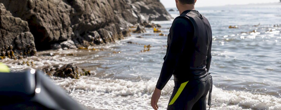
Jet ski rider assessing sea before launch

Why PWC Sea Condition Ratings Matter for Rider Safety

Sea-condition ratings matter because they tell you, before you ever launch, whether your craft, your skill level, and your planned route can handle what the water is actually doing that day. A rating consolidates wind speed, wave height, swell period, and current into a single operational risk snapshot. That matters more on a PWC than on almost any other vessel: a forecasted “seas 3 to 4 feet” can hide individual waves running 1.5 to 2 times higher than the average, and a 21-foot boat shrugs that off in a way a 700-pound jet ski cannot.

Key Takeaways

Sea-condition ratings work because they convert wind, wave height, swell period, and current into a single risk estimate riders can match against skill level before launch.

Point Details
Ratings combine multiple inputs Wind, significant wave height, swell period, visibility, and current all shape actual risk.
Averages hide spikes Individual waves can run 1.5 to 2 times higher than the posted significant wave height.
Cross-check live data Confirm NWS forecasts against nearby NDBC buoy readings before and during a ride.
Match thresholds to skill Beginners, intermediate riders, and advanced racers need different go/no-go limits.
Act early on warning signs Wind shifts, opposing currents, and building whitecaps call for an immediate return to shore.

Where to Check Conditions Before You Launch

  • NWS marine forecasts for zone-by-zone wind, seas, swell, and active warnings.
  • NDBC buoy observations for real-time conditions near your launch point.
  • Marine radar apps for tracking incoming weather cells in real time.
  • Local tide tables to time current windows against your ride plan.

Table of Contents

What a Sea Condition Rating Actually Measures

A rating isn’t one number. It’s a blend of five inputs, and understanding each one changes how you read a forecast before you trailer the PWC anywhere.

  1. Wind speed and direction — the primary driver behind wave buildup and the fastest-changing variable on the water.
  2. Significant wave height (“seas”) — the average height of the largest one-third of waves, not the tallest wave you’ll actually see.
  3. Swell height and period — how much energy is moving through the water and how far apart the waves arrive, measured in seconds.
  4. Visibility — fog, haze, or glare that shortens your reaction window to other traffic or obstacles.
  5. Current and tide interaction — how moving water changes wave steepness independent of wind.

The National Weather Service’s sea state guidance still relies on Beaufort-based visual observation for a reason: instruments aren’t always available, and a trained eye reading whitecap coverage and wave crest behavior can estimate conditions almost as reliably as a buoy reading.

Pro Tip: If your PWC has no onboard weather display, watch the horizon for whitecap frequency. Scattered whitecaps generally track to Beaufort force 4 (11 to 16 knots); widespread whitecaps with spray mean you’re already past comfortable PWC range for most riders.

Sea with whitecaps and wind spray visible

How Wind, Waves, Swell, and Currents Change PWC Handling

Forecast numbers translate directly into what your hands and body feel on the water, and the translation isn’t linear. Short-period wind chop, the kind generated by local gusts over a few miles of fetch, hits a PWC hull in fast, steep pulses that punish your wrists and lower back. Long-period ocean swell, even at the same reported height, lifts and rolls the craft more gently and gives you time to adjust trim.

  • A beginner on a rented 110hp PWC nearshore starts losing confident control once seas exceed roughly 1 to 2 feet with any wind chop layered on top.
  • An experienced racer running an offshore lap can manage 3 to 4 foot seas with a long swell period, but the same racer gets punished by short, breaking 2-footers stacked close together.
  • Fatigue compounds fast: constant micro-corrections to stay upright in chop burn forearm and core strength far quicker than steady cruising, and seasickness risk climbs with irregular, confused seas.
  • Reduced visibility from spray or fog cuts your reaction time to other watercraft, buoys, and shoreline hazards.

The reported significant wave height is only an average. Individual waves in that same wave field can run 1.5 to 2 times higher than what’s posted, which means a “calm-sounding” 2-foot forecast can deliver an occasional 3.5 to 4 foot wave that catches an inattentive rider off guard. Opposing currents and wind can also stack wave height and whitecap formation quickly, turning a moderate afternoon into a rough one within an hour.

How to Use Ratings to Plan Your Ride

Turning forecast data into a launch decision comes down to checking the right sources and applying consistent thresholds instead of guessing from the shoreline. The NWS marine forecast portal gives you zone-by-zone wind, seas, swell, and visibility, along with any small craft advisories that override routine planning. Cross-check that forecast against NDBC buoy observations near your launch point. Forecasts lag reality, and a nearby buoy tells you what’s happening right now, not six hours ago.

Wind thresholds are a useful shorthand once you know them. Small craft advisories typically escalate around key wind thresholds commonly used to define warning levels (https://primonautic.com/blog/marine-weather-forecast-reading-sea-conditions-explained), and those breakpoints work reasonably well for PWC decision-making too, adjusted down for rider skill.

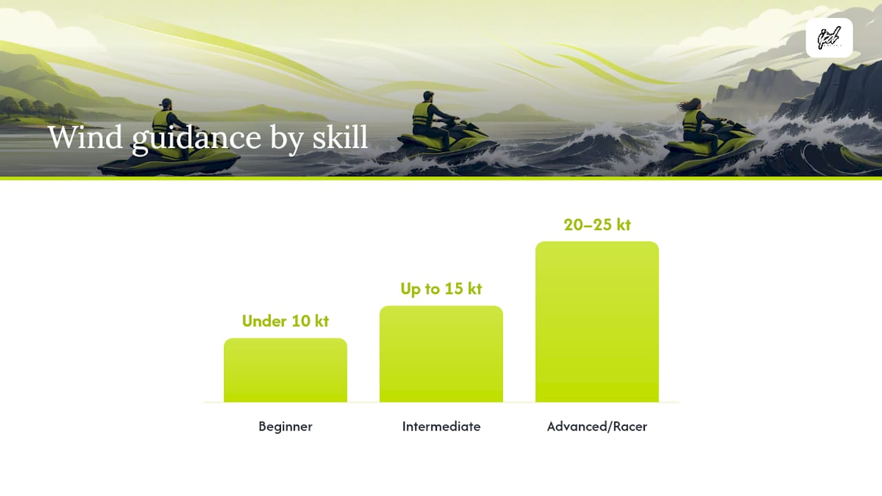
Rider Skill Wind Guidance Significant Wave Height Swell Period Note
Beginner Under 10 knots Under 1 foot Any period; avoid mixed chop
Intermediate Up to 15 knots Up to 2 feet long period preferred
Advanced/Racer Up to 20 to 25 knots Up to 3 to 4 feet Comfortable with 6+ seconds

Diagram showing skill levels matched to wind, wave, and swell limits

Run this workflow before every launch: check the NWS zone forecast, confirm it against the nearest live buoy, note the current tide stage and whether current opposes wind, match the numbers to your skill band above, and only then commit to a route.

Watching Conditions on the Water and Knowing When to Turn Back

Forecasts describe averages. What actually threatens a ride is a sudden shift the forecast didn’t fully capture. Watch for a rapid change in wind direction, current running against wind (which steepens waves fast), a jump in whitecap density, dropping visibility, or a new swell train arriving from a different angle than the wind sea.

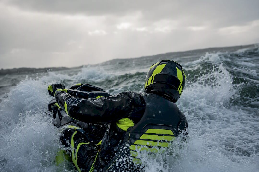
PWC rider turning back in rough water

When any of these show up, act immediately rather than waiting to see if it passes. Slow down, change heading to find a lee shore or wind shadow, and start working toward the nearest safe landing point. Keep a VHF radio or charged phone accessible, and always have a float plan on file with someone onshore before you leave.

Pro Tip: Build a rolling mental model as you ride: compare what you see every 10 to 15 minutes against your launch-time forecast. If two or more indicators (wind, wave steepness, visibility) have moved against you at the same time, that’s your cue to head in, not push further out.

A One-Page Pre-Ride Checklist for PWC Riders

Print this, screenshot it, or keep it on your phone. Run through it every single time, even on familiar water.

  • Check the NWS marine zone forecast for wind, seas, swell, and active warnings.
  • Confirm the nearest NDBC buoy reading matches the forecast within reason.
  • Check tide tables and note whether current will oppose or align with wind during your ride window.
  • Rate your own skill honestly against the go/no-go table and pick a route accordingly.
  • Confirm safety gear: life vest, kill switch lanyard, whistle, and communication device.
  • File a float plan with a specific return time and location.

For coastal launches specifically, IPD Racing’s jet ski coastal riding safety prep guide expands on tide timing and shoreline hazards, and the open water safety gear guide covers what belongs in your kit before you ever leave the dock.

Common Misconceptions About Sea Condition Ratings

The most common mistake riders make is checking a land weather app instead of a marine forecast. Land forecasts don’t account for wave height, swell period, or marine-specific advisories, and the wind reading at an inland airport rarely matches what’s happening two miles offshore.

The second mistake is underestimating current. A tide window that looks calm on the surface can be moving fast enough to steepen waves dramatically when it runs against wind direction, an effect that catches riders off guard near inlets and passes. A third: mistaking calm-looking water near shore for calm conditions overall, when local wind chop and incoming swell from a distant system are two separate things that stack on top of each other.

Pro Tip: Advanced riders pushing offshore limits should build in a wider buffer than the basic thresholds suggest. Since individual waves can spike 1.5 to 2 times above the significant wave height, treat any forecast near your personal ceiling as if it’s already at that ceiling.

Ready to Match Your PWC to Rougher Water?

Reading the ratings correctly is half the equation. The other half is making sure your craft is actually tuned to handle the conditions you’re comfortable riding in. IPD Racing’s guide on watercraft tuning best practices for racers walks through setup adjustments that improve handling in chop and swell, and the full performance parts shop carries the hull, steering, and handling upgrades that make a real difference once seas start building past beginner thresholds. For riders weighing hull response in rougher water, IPD Racing’s breakdown of why PWC hull rocker matters is worth reading before your next upgrade decision. If you’re also managing risk beyond the ride itself, Diamondback Insurance’s guide to boat insurance and tow services covers what a contingency plan should include if conditions turn faster than expected.

What Actually Matters Most in Sea Condition Ratings

Most PWC safety content treats wind speed as the only number worth watching. That’s incomplete. Swell period changes the entire character of a ride at the same reported wave height, and it gets buried in guides that focus purely on knots. A 3-foot sea with a 12-second period rides completely differently than a 3-foot sea with a 6-second period, and riders who only check wind miss that distinction every time.

The bigger gap in conventional advice is treating significant wave height as a ceiling instead of an average. It’s an average of the top third of waves, which means the water will occasionally throw something meaningfully larger at you, and riders who plan right up to the posted number leave themselves no margin.

If you take one thing from this: build your skill-based thresholds with that variance already priced in, not as an afterthought. Check the forecast, cross-check the nearest buoy, and treat any number close to your limit as if it’s already past it.

Frequently Asked Questions

Why do PWC riders need marine forecasts instead of regular weather apps?
Standard weather apps report land conditions and skip wave height, swell period, and marine advisories entirely. The NWS marine forecast is built specifically for water-based decisions.

What wind speed is too much for a PWC?
It depends on skill level, but beginners should stay under 10 knots, intermediate riders can handle up to 15 knots, and advanced riders can often manage 20 to 25 knots if swell period is favorable.

Why does significant wave height matter more than it sounds?
It’s an average of the largest third of waves, so individual waves can run up to twice that height. A 2-foot forecast can still produce a 4-foot wave.

How often should I check buoy data during a ride?
Check before launch and again every 30 to 60 minutes if conditions seem to be shifting, since forecasts lag real-time buoy readings.

Does current really affect wave height that much?
Yes. Wind blowing against a strong current steepens waves noticeably, especially near inlets and passes, even when the wind speed alone would suggest calm conditions.

Sources

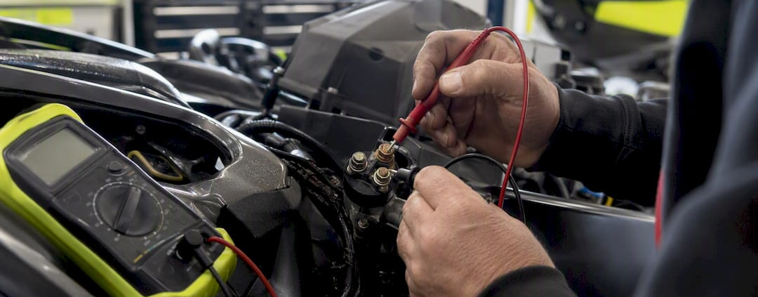
Hands testing PWC starter solenoid with multimeter

How PWC Electric Start Works: A Diagnostic Guide

A PWC electric start is a two-stage electrical system. A low-current start switch energizes a starter solenoid, which then closes a high-current path so a 12-volt battery can send full amperage to the starter motor and crank the flywheel.

Three parts do almost all the work: the battery, the starter solenoid (a relay that acts as a heavy-duty switch), and the starter motor itself. If you press the button and hear one click but nothing turns over, that click tells you the solenoid coil energized but the high-current side failed to deliver power. Reputable aftermarket suppliers like IPD Racing and Protorque build replacement starters and solenoids specifically because these two parts fail more often than the wiring around them.

  • Battery: stores and supplies the 12-volt charge that cranks the engine.
  • Starter solenoid: switches high current on command from a low-current signal.
  • Starter motor: converts that current into mechanical force on the flywheel.

Key Takeaways

A PWC electric start relies on a low-current control circuit triggering a solenoid, which then delivers full battery current to the starter motor to crank the engine.

Point Details
Two-stage system A low-current switch energizes the solenoid, which closes a high-current path to the starter motor.
One click, no crank Usually means the solenoid coil worked but the high-current side failed or the battery sagged.
Check voltage first Resting voltage near 12.6 volts and under-load readings above 9 to 10 volts confirm battery health.
Pull codes before parts ECU lockouts often stem from a bad sensor or connector, not a failed component.
Upgrade path Protorque starters from IPD Racing offer a direct-fit replacement when bench tests confirm starter failure.

Table of Contents

Key Components in a PWC Electric-Start System

Every electric start system on a jet ski runs through the same basic chain of parts, whether it’s a Sea-Doo, a Yamaha, or a Kawasaki. Knowing what each piece does makes troubleshooting a lot less guesswork and a lot more process.

  • Battery: usually a sealed 12-volt unit; weak cells cause slow or no cranking.
  • Main battery terminals: corrosion or loose clamps here mimic a dead battery.
  • Starter motor: spins the flywheel; seizes internally after water intrusion or age.
  • Starter solenoid/relay: the switch between low-current control and high-current power; contacts pit and stick over time.
  • Start/stop switch and lanyard kill switch: the rider-facing controls that open or close the control circuit.
  • Safety interlocks (neutral, hood, or seat sensors): block start signals when a condition isn’t met.
  • Fuses/circuit breaker: protect the low-current side; a blown fuse looks identical to a dead switch.
  • Wiring and main power cables: carry both signal and heavy current; chafe points and connectors corrode.
  • Ground points: often overlooked, and a poor ground can produce symptoms that look like a failed ECU.
  • ECU interlocks: software-side logic that can block starting even when every mechanical part is fine.

When a starter finally gives out for good, a Protorque Jet Ski starter motor is a straightforward drop-in path back to reliable starts, and we’ll cover fitment specifics further down.

What Happens Electrically When You Press Start?

The sequence from button press to flywheel rotation happens in well under a second, but each link in the chain has its own failure signature.

  1. You press the start switch. This closes a low-current control circuit. No click at all usually points to a dead switch, blown fuse, or an open safety interlock.
  2. The solenoid coil energizes. You should hear a distinct click. If you don’t, test for voltage at the solenoid’s small control terminal.
  3. The solenoid closes its heavy-duty contact. This is the moment the two-stage design does its job: the solenoid acts as a high-current switch so the start button itself never has to carry starter amperage.
  4. The battery sends full current to the starter motor. A click followed by silence commonly points to solenoid contact wear or the battery sagging under load.
  5. The starter engages its bendix or pinion gear and physically turns the flywheel. Slow, labored cranking usually means high resistance somewhere in the circuit rather than a dead battery outright.
  6. The engine fires, and the starter disengages automatically once the flywheel is spinning under its own power.

Statistic Callout: A weak battery is one of the most common root causes owners overlook. Many PWCs need resting voltage around 12.6 volts or higher just to crank reliably, even when the battery has enough charge left to run the gauges and lights.

Why Won’t It Start Even When the Battery and Starter Look Fine?

Sometimes every component tests good in isolation, and the craft still won’t crank. That’s almost always a safety interlock or an ECU protective lockout, not a mechanical failure.

  • Lanyard kill switch: if it’s not seated, the control circuit stays open regardless of battery or starter condition.
  • Neutral or park switch: some models won’t allow cranking unless this switch confirms the right position; corrosion or a stuck contact breaks the signal.
  • Hood or seat sensor: a common source of no-start after heavy wave exposure, since water intrusion corrodes these connectors first.

Beyond the switches, the ECU itself can block starting as a protective measure when a sensor reads out of range or the rectifier/regulator shows a fault. Owners often assume a stored code means a catastrophic failure, when it’s frequently a corroded connector or a marginal sensor reading triggering a conservative shutdown.

Pro Tip: Always pull stored fault codes, or at minimum check for a warning light, before you replace any electrical component to follow best practices in diagnostics and solutions for service engine lights." Chasing a phantom starter problem when the real issue is a $12 sensor wastes both time and money.

How Do You Test a PWC Starter System Step by Step?

Before touching anything, disconnect the battery, put on eye protection, remove jewelry, and make sure the craft can’t accidentally fire while you’re working near the flywheel.

  1. Check resting battery voltage. A healthy battery reads around 12.6 volts at rest, climbing to roughly 13.5 to 14.5 volts while charging.
  2. Check voltage at the starter power stud while someone presses start. A voltage check under load is the single most informative quick test because it separates a battery problem from a starter or wiring problem in one reading.
  3. Listen for the solenoid click, then test for coil voltage at its small control terminal to confirm the low-current side is doing its job.
  4. Run a voltage-drop test across the battery positive cable to the starter stud, and across the ground path to the starter body. Excess resistance here shows up as heat and a slow crank long before it shows up as a dead short.
  5. Bench test the starter and solenoid separately. Shorting the two heavy studs on the solenoid with caution will bypass the control circuit entirely; if the starter cranks when shorted, the motor itself is fine and the fault sits upstream in the solenoid, switch module, or wiring.
  6. Inspect and clean ground points, then check the fuse or circuit breaker for corrosion or a hairline break that a visual glance can miss.

Statistic Callout: Under-load voltage significantly below normal during cranking points to a weak battery or serious resistance in the circuit, not a bad starter motor.

  • Stop and let a shop handle it if you find internal starter mechanical failure, a hydrolocked engine, or high-current harness damage that needs proper crimping and heat-shrink work.
  • Use insulated tools and full eye protection any time you’re bench testing or shorting solenoid studs; sparks and high current are normal parts of the process, not a sign something’s wrong.

When Should You Replace the Starter, Solenoid, or Battery?

Testing tells you which part failed. These thresholds tell you when repair stops making sense and replacement takes over.

  • Replace the battery if resting voltage sits below 12.4 volts, or if voltage sags below 9 to 10 volts the moment you hit start.
  • Replace the solenoid if it clicks reliably but never passes power, or if it sticks closed intermittently, a known issue on older solenoids with metal backing plates that corrode internally.
  • Replace the starter if a bench test shows no torque at all, or if it spins freely without engaging the flywheel, a classic sign of a worn bendix or pinion.

When you’re shopping for a replacement, check three things: fitment by make, model, and year; the starter’s current rating against your engine’s cranking demands; and whether it’s an OEM-style unit or an aftermarket bolt-on. A Protorque starter is built as a direct-fit aftermarket option for a wide list of platforms, with a fully molded housing that avoids the corrosion issues older metal-backed solenoids are prone to. If you’re not certain about compatibility, confirm fitment before ordering rather than guessing from a parts number alone.

Routine Maintenance That Prevents Starting Problems

Most starting failures trace back to neglect rather than a defective part. A short seasonal routine catches nearly all of it before it strands you on the water.

  • Clean battery terminals, then torque and protect main battery cables against corrosion.
  • Remove, clean, and re-torque ground points; corroded grounds are one of the most overlooked failure points on marine electrical systems and often get misdiagnosed as sensor or ECU faults.
  • Check the fuse box for water intrusion, and test the lanyard and start button for clean, reliable contact.
  • Confirm charging voltage runs 13.5 to 14.5 volts while the engine is running.
  • Keep the battery on a smart maintainer during storage, run the craft periodically, and drain or replace old fuel so a fuel issue doesn’t get mistaken for an electrical no-start.
  • Seal exposed connectors with dielectric grease and re-check booted connections after any heavy spray session.

Essential Tools and Diagnostic Readers You’ll Need

A basic kit covers nearly every test above: a quality multimeter with DC voltage and continuity settings, a 12-volt jump pack (used cautiously), insulated hand tools, a battery terminal cleaner, dielectric grease, and a torque wrench for terminal hardware. Many modern PWCs need dealer-level tools to pull ECU diagnostic trouble codes, so check for a model-specific code reader before assuming you need one. Pull codes first, always, before you buy replacement parts. When you do need hardware, Protorque starters and related parts cover most of what a season of wear and tear will throw at you.

What Racers Learn About Starter Failure at the Track

At race events, starter failures cluster around heat cycling and high-frequency restarts, not age alone. That pattern is exactly why racers often move to higher-current Protorque units before a stock starter gives out mid-heat. If you’re upgrading wiring or harness capacity alongside the starter, get a shop to handle the high-current connections.

Technician installing PWC Protorque starter at race pit

Get the Right Starter Parts Without the Guesswork

Diagnosing a no-start is only half the job. Once you’ve isolated the failure, IPD Racing carries the parts to fix it right the first time, rather than swapping components on a hunch.

IPD Racing

IPD Racing stocks Protorque starter motors built as direct-fit replacements across a wide range of Sea-Doo, Yamaha, Kawasaki, and Polaris platforms, so you’re not stuck hunting for a discontinued OEM part. Before you order, check fitment by make, model, and year, and reach out to tech support if anything about your setup looks non-standard. Beyond starters, the full performance parts catalog covers solenoids, battery hardware, and the wiring accessories that keep an electric start system reliable season after season.

Frequently Asked Questions

How does a PWC electric start work if the battery seems fine but nothing happens?
A charged battery doesn’t guarantee a good start signal. Check the lanyard kill switch, neutral interlock, and fuses first, since any open safety circuit stops the sequence before it reaches the solenoid.

Diagram of PWC electric start safety circuit and components

What does a single click from the solenoid mean?
It means the low-current control circuit worked and the coil engaged, but the high-current path failed to deliver power to the starter. That points to a worn solenoid contact, a corroded cable connection, or a battery sagging under load.

Can a bad ground really stop a PWC from starting?
Yes. A corroded or loose ground point adds resistance that can mimic a failed sensor or a weak battery, and it’s one of the most commonly overlooked fixes during routine maintenance.

Should I replace the starter or the solenoid first?
Bench test both separately. Shorting the solenoid’s heavy studs isolates whether the starter motor itself works; if it cranks fine that way, the solenoid or its control wiring is the actual problem.

When does an upgrade to a Protorque starter make sense?
Consider it once a bench test shows a worn or seized starter, or if you’re racing and cycling starts frequently enough that heat buildup is shortening the stock unit’s life.

Sources

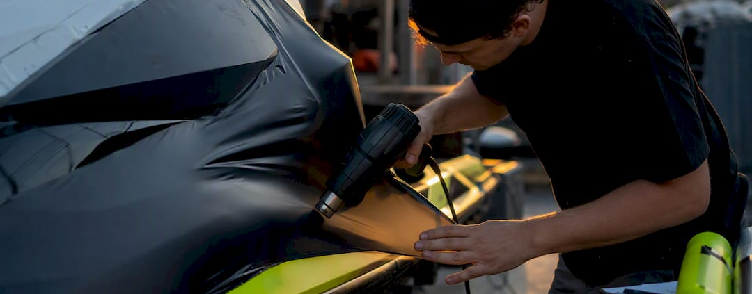
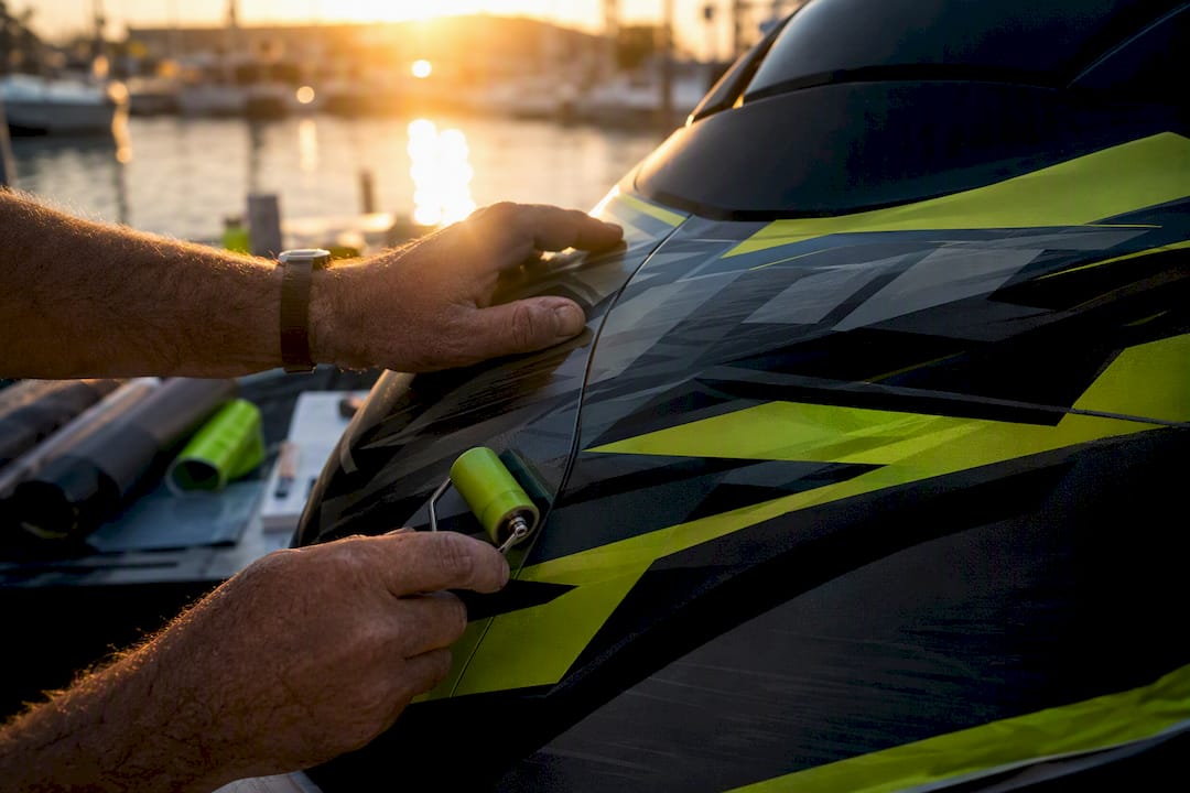
Hands applying vinyl wrap on jet ski hull

Jet Ski Wrap Cost: Realistic Price Ranges & How to Save

A jet ski wrap typically costs between $500 and $3,800 depending on coverage and material grade, with most owners landing around $2,000 for a full professional install. DIY kits run far cheaper, usually $300 to $800, but demand real time and a steady hand on curved hulls.

If your budget is tight and you’re comfortable with a squeegee and a heat gun, a DIY kit is the smarter play. If you want a complex custom design or expect the wrap to last through several riding seasons, a professional install earns its premium.

  • DIY kit (partial or full): $300–$800
  • Professional install (standard, single-color): $1,200–$2,000
  • Premium custom printed wrap: $2,500–$3,800+

Cost Insider’s pricing breakdown puts the average total project at $2,000, with materials alone running $400 to $1,200 depending on vinyl grade.

Key Takeaways

Jet ski wrap costs typically fall between $500 for a basic DIY kit and $3,800 for a premium custom professional install, with material grade and coverage level driving most of the variance.

Point Details
Know your price band Budget $300–$800 for DIY kits, $1,200–$2,000 for standard pro installs, and $2,500–$3,800+ for premium custom work.
Material grade changes longevity Marine-grade cast vinyl costs more upfront but resists fading and lifting far longer than budget film.
Measure before you buy Calculate square footage per panel, add 15 to 20% for waste, then round up to full yards or a pre-cut kit size.
Ask for itemized quotes Breaking out materials, labor, and prep costs reveals which fees are negotiable.
Support your wrap with the right parts IPD Racing offers model-specific galleries and parts, like the Yamaha Squarenose Superjet gallery, to plan coverage and fitment before you commit to a design.

Table of Contents

What Does Jet Ski Wrap Cost Actually Cover?

A jet ski wrap is a layer of adhesive vinyl film applied over the hull and body panels, either to change the color, add graphics, or protect the factory gelcoat underneath. The cost you pay covers three things: the vinyl itself, the printing or cutting of your design, and the labor to stretch, heat, and trim it around every curve of your PWC.

Vinyl comes in two main types. Cast vinyl is thinner, more conformable, and holds up better on the tight curves of a jet ski hull. Calendared vinyl is cheaper but stiffer, and it tends to lift or crack sooner on compound curves. Most reputable shops use cast vinyl from established manufacturers like 3M or Avery Dennison, both of which make marine-rated films built to handle UV exposure and constant water contact.

Finish choice moves price too:

  • Gloss or matte: the baseline finish, included in most standard quotes
  • Chrome or holographic: adds shine and depth, usually a $200–$300 upcharge
  • Textured 3D or carbon fiber: mimics a molded surface, priced as a premium add-on
  • Protective laminate overlay: adds scratch and UV resistance, often 15–20% to the material cost

Brand and grade matter because a $5 per square foot budget vinyl might look identical to a $15 per square foot marine-grade film on day one, but only one of them survives five seasons of saltwater and sun.

What Drives the Total Price of a Jet Ski Wrap?

Six variables decide whether your wrap lands at $500 or $3,800, and most of them are within your control.

Material quality and finish is the biggest swing factor. Marine-grade cast vinyl from an established brand costs more upfront but resists fading and lifting far longer than a generic film, according to ShunAuto’s cost breakdown.

Coverage level scales both material and labor. A partial wrap covering just the hood or trim panels might use one roll of vinyl. A full-hull wrap covering every visible panel can run three to four times the material and double the install hours.

Design complexity matters more than most people expect. A single flat color wraps fast. A multi-color printed design with pattern matching across seams requires careful alignment on curved surfaces, which eats labor hours and increases the risk of a misaligned seam that has to be redone.

Hands aligning patterned vinyl wrap on jet ski seam

Surface prep and old-wrap removal are often the hidden line item in a quote. Stripping an old wrap, sanding rough spots, and repairing gouges or gelcoat damage typically adds $100 to $300 before a single sheet of new vinyl goes on.

Geography and shop skill level shift labor rates regionally, and rush jobs almost always carry a surcharge.

Labor hours for a mid-size jet ski typically run 8 to 20 hours depending on complexity, billed at $60 to $120 per hour in most markets. Do the math on a 15-hour job at $90 an hour and labor alone hits $1,350, before materials.

Pro Tip: Ask every shop for an itemized quote broken into materials, labor, and prep. A vague lump-sum number hides which line items you can actually negotiate down.

How Much Does a Jet Ski Wrap Cost in Real Scenarios?

Three example budgets show how coverage and material choice change the final invoice.

Scenario 1: Small partial DIY kit. You buy a pre-cut kit for the hood and side panels, install it yourself over a weekend. Vinyl and application tools run $300 to $600, per ShunAuto’s DIY range. No labor cost since you’re doing the work, but budget a few hours for mistakes on your first attempt.

Scenario 2: Standard full-hull, single-color professional install. A shop strips your old graphics, preps the surface, and applies a solid-color cast vinyl wrap across the entire hull. Materials run $400 to $700, labor lands at $600 to $1,200 for roughly 10 to 15 hours, and prep adds another $100 to $200. Total: roughly $1,200 to $2,000, matching the average project cost Cost Insider reports.

Scenario 3: Premium custom printed full-hull wrap with textured finish. This is the top end: a fully custom printed design, chrome or holographic accents, and a textured 3D finish. A base custom graphics kit alone can start around $610, with chrome or holographic base upgrades adding $260 to $290 more, before labor. Add professional installation with pattern matching across curves and total project costs commonly reach $2,500 to $3,800.

Cost Component Low Average High
Materials (vinyl, laminate) $300 $700 $1,200
Labor $400 $900 $2,000
Design/setup (custom print) $0 (stock) $200 $610+
Prep/old-wrap removal $50 $175 $300
Total project $1,200 $2,000 $3,800

Diagram of jet ski wrap cost components and their ranges

Figures reflect Cost Insider’s component ranges for a standard mid-size PWC; custom design fees vary by shop and complexity.

How Much Vinyl Do You Actually Need?

A standard 2 to 3 seat jet ski typically needs 30 to 50 square feet of vinyl to cover the full hull, hood, and side panels. Larger three-seat or tow-sport models can push that to 60 to 80 square feet. Partial wraps covering just the hood or trim panels usually need 10 to 20 square feet.

Measuring accurately before you order is the single biggest way to avoid a mid-project material shortage.

Materials checklist for a DIY install:

  • Vinyl (cast, marine-grade recommended)
  • Protective laminate, if not pre-laminated
  • Application fluid (soapy water solution)
  • Heat gun or propane torch for stretching around curves
  • Squeegee with felt edge
  • Precision blade or snap-knife for trimming
  • Microfiber cloth for surface prep

Here’s a simple way to figure out how much to buy:

  1. Measure the length and width of each panel (hood, sides, rear) in inches.
  2. Convert each panel’s area to square feet, then add all panels together.
  3. Add 15 to 20% for waste, overlap, and mistakes.
  4. Convert total square feet to linear yards based on your vinyl roll’s width (most rolls run 24 to 60 inches wide).
  5. Round up to the nearest full yard, since most suppliers sell by the yard or in fixed roll lengths.

Pre-cut kits sized for specific PWC models eliminate most of this math. Rvinyl’s guidance notes that measured, pre-cut kits reduce both waste and the beginner errors that come with cutting your own patterns from a bulk roll.

Is DIY Jet Ski Wrapping Worth the Time Savings?

DIY wrapping saves real money, but it costs real hours, and the learning curve on a curved hull is steeper than wrapping a flat surface like a laptop or a car hood.

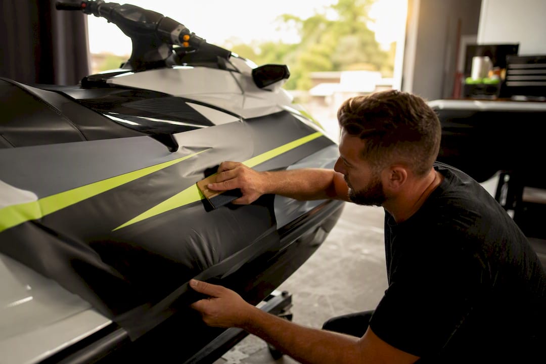
Person smoothing DIY vinyl wrap on jet ski

Expect a first-time DIY full wrap to take a full weekend, sometimes longer. The hardest part is stretching vinyl around compound curves near the nose and stepped hull sections without creating bubbles or wrinkles. A heat gun helps the vinyl conform, but overheating it can stretch the film past its printed registration, which ruins alignment on multi-color designs.

Tools you’ll need and rough costs:

  • Heat gun: $20–$40 (or rent one for a single project)
  • Precision squeegee set: $15–$25
  • Snap-blade knife and extra blades: $10
  • Surface prep solution: $10–$15

Professional shops charge more because their workflow includes steps most DIYers skip: creating a digital template of your exact hull shape, test-fitting panels before final application, and matching printed patterns precisely across seams. That precision is also why most shops back their work with a workmanship warranty.

The most common DIY failure mode is lifting edges from insufficient heat during application, or bubbling from trapped air. Both are fixable, but a redo eats into whatever you saved versus paying a pro the first time.

Pro Tip: If your design has any multi-panel graphics that need to align across a seam, hire a pro. Pattern matching on a curved hull is one of the hardest skills to get right without practice.

Wrap or Repaint: Which Costs Less Long Term?

A vinyl wrap generally costs less upfront than a professional paint job and offers more flexibility if you want to change your look again later. Professional marine paint jobs typically run $1,000 to $3,000 or more, while a full custom wrap lands in the $600 to $1,400 range for most installs.

  • Durability: paint can last longer if properly maintained, but chips and scratches show immediately; vinyl resists minor scuffs but is more vulnerable to UV fading over years of direct sun exposure
  • Maintenance: wraps need occasional cleaning with non-abrasive soap; paint may need periodic wax and buffing
  • Reversibility: a wrap can be removed and replaced without touching the underlying gelcoat; paint is permanent unless you repaint again

Choose repaint when you want a permanent color change or need to cover structural gelcoat repairs. Choose a wrap when you want protection for the factory finish, a custom look you might change again, or a lower upfront cost.

Pro Tip: A wrap can actually protect resale value better than paint, since it shields the original factory gelcoat underneath rather than replacing it.

How Can You Lower Your Jet Ski Wrap Cost?

Small scheduling and material decisions can shave hundreds off a quote without cutting corners on quality.

  • Book during off-season: shops often have lighter schedules in fall and winter, and some offer lower labor rates to fill open bays
  • Choose partial coverage: an accent wrap on the hood and sides costs far less than a full-hull job and still refreshes the look
  • Use a pre-cut kit: sized-to-model kits reduce waste and skip the design/setup fee a fully custom print requires
  • Pick mid-tier marine-grade vinyl: it balances cost and longevity better than bargain films that fade within a season
  • Bundle services: ask if prep, wrap, and a protective laminate coat can be quoted together for a package discount
  • Request an itemized quote: breaking out materials, labor, and prep makes it easier to spot which fees are negotiable

How IPD Racing Supports Your Wrap Project

IPD Racing carries the parts and accessories that round out a wrap project beyond the vinyl itself, from traction mats to handle pole components that need to match your new graphics scheme. Browsing model-specific galleries like the Yamaha SuperJet graphics gallery or the Yamaha WaveBlaster gallery gives you a realistic sense of coverage levels and finish options before you commit to a design.

  • Model-specific graphics galleries showing coverage and finish examples
  • A shop by model catalog for finding compatible parts alongside your wrap
  • Direct contact support for questions on fitment or compatible upgrades

Whether you’re doing a full DIY install or coordinating with a shop, having the right supporting parts on hand, matched to your PWC model, cuts down on delays and mismatched hardware once the wrap goes on. If you’re unsure what fits your specific model, reach out through IPD Racing’s contact page before you order.

Do Jet Ski Wraps Come With a Warranty?

Most professional shops offer a workmanship warranty separate from the material warranty, and the two cover different failures. A shop’s workmanship warranty, typically 6 to 12 months, covers lifting edges, bubbling, or seam separation caused by installation error. Material warranties from vinyl manufacturers like 3M or Avery Dennison typically cover fading or cracking under normal use, often for several years, but only when the vinyl was installed according to the manufacturer’s specifications.

DIY installs generally carry no workmanship warranty at all since there’s no shop backing the labor. If your DIY wrap fails from a heat-application mistake, you’re covering the repair or full re-wrap yourself.

Ongoing maintenance costs are modest but real. Rinsing with fresh water after saltwater exposure prevents salt crystal buildup that can dull the finish over time. Avoid high-pressure washers held too close to seams, since they can force water underneath the vinyl edge and cause premature lifting. A vinyl-safe UV protectant applied every few months extends color life, particularly on darker or printed finishes that fade faster under direct sun.

Budget for a re-laminate or partial touch-up around year three to four on a heavily used PWC, especially in high-UV climates. That’s typically far cheaper than a full re-wrap and can extend the life of your original graphics by another season or two.

Is a Pro Wrap Worth the Extra Cost?

A professional install earns its price when your design involves multi-panel pattern matching or when you plan to keep the PWC long enough that durability matters more than upfront savings. For a simple single-color accent wrap, a DIY kit gets you most of the visual payoff for a fraction of the cost.

The most common regret I hear about isn’t overspending. It’s underspending on vinyl grade to save $150 upfront, then redoing the whole wrap two summers later when the cheap film fades and cracks first. Marine-grade cast vinyl from a reputable brand almost always pays for itself before the wrap’s second season ends.

Ready to Complete Your Jet Ski’s Look?

A wrap changes your jet ski’s appearance, but the parts underneath it are what keep it running the way you want. IPD Racing stocks the performance and handling upgrades that pair naturally with a fresh graphics job, from hull and steering components to traction and footing products that hold up under the same conditions your new vinyl has to survive.

IPD Racing

If you’re planning a wrap alongside other upgrades, browsing IPD Racing’s hot products performance parts page is a practical way to see what else riders typically bundle with a graphics refresh. For model-specific fitment questions or help finding compatible accessories before your wrap goes on, shop by model to find parts matched to your exact PWC.

Frequently Asked Questions

How much does it cost to wrap a jet ski?
Most full professional wraps cost between $1,200 and $2,000, though premium custom designs can reach $3,800 or more. DIY kits typically run $300 to $800.

Is it cheaper to wrap or paint a jet ski?
Wrapping is usually cheaper upfront, with full custom wraps running $600 to $1,400 compared to professional paint jobs at $1,000 to $3,000 or more.

How long does a jet ski wrap last?
Marine-grade cast vinyl typically lasts several years with proper care, though exact longevity depends on sun exposure, saltwater rinsing habits, and vinyl grade.

Can you wrap over an old wrap?
It’s not recommended. Old wraps should be removed first, which typically adds $100 to $300 to a project, since wrapping over existing vinyl traps imperfections and shortens the new wrap’s lifespan.

How much vinyl do I need for a jet ski wrap?
A standard 2 to 3 seat model typically needs 30 to 50 square feet, while larger models can require 60 to 80 square feet.

Do jet ski wraps come with a warranty?
Many professional shops offer a workmanship warranty covering installation defects, typically 6 to 12 months, separate from the vinyl manufacturer’s material warranty against fading or cracking.

Sources

Tools and equipment for jet ski hull setup

Free-Ride Hull Setup Steps for Tuners: A Step-by-Step Guide

Getting a hull ready for free-ride performance comes down to four moves: measure the existing geometry, gather your tools and backing hardware, position ballast and shapers, and confirm everything with a measured sea trial. Skip any one of these and you’re guessing instead of tuning.

Here’s the high-level sequence before you touch a drill:

  • Measure rocker, transom height, beam, and draft, and log baseline speed-to-RPM numbers.
  • Assemble tools, backing plates, and sealant before disassembling anything.
  • Choose temporary, semi-permanent, or structural modifications based on hull type.
  • Position ballast and shapers, then run a controlled sea trial to confirm the wake.
  • Adjust in small increments and re-test rather than making one big change.

Confirm your hull’s USCG capacity plate before adding ballast weight, and use backing plates on any through-bolted hardware. Thin fiberglass cracks fast without one.

Key Takeaways

A free-ride hull setup succeeds when measured baseline geometry, correctly backed hardware, and incremental ballast and shaper adjustments are confirmed through repeated sea trials rather than one-shot guesswork.

Point Details
Measure before modifying Record rocker, transom height, beam, and draft, plus baseline speed-to-RPM numbers, before touching tools.
Backing plates are not optional Any through-bolted hardware on fiberglass thinner than a quarter inch needs a backing plate to avoid stress cracks.
Ballast ratio starts near 2:1 Rear-to-bow ballast distribution near 2:1 is the standard starting point for most surf setups.
Tune in small increments Adjust wedge, trim, or ballast one step at a time and re-test rather than making large changes at once.
IPD Racing supplies the hardware IPD Racing’s ProWatercraft and performance parts lines carry mounting hardware and props sized for PWC hull modifications.

Table of Contents

Tools and Prep Before You Cut, Drill, or Add Ballast

A free-ride hull conversion lives or dies on prep work, not the drilling itself. Gather your tools first: a drill with sharp bits, a chamfer bit, backing plates, backing washers and nylock nuts, marine sealant, 3M tape, sandpaper or a file, mounting cleats for strap attachments, ballast bags with a pump, a wakesurf shaper mounting kit, and a prop puller if you’re touching the drive.

Before disassembly, document your hull’s baseline: rocker, transom height, beam, draft, the USCG capacity plate rating, access space under the deck, and any factory wiring or plumbing that runs through the area you’re modifying. Manufacturer installation manuals for wake tower and hull hardware consistently flag gelcoat chipping and wiring interference as the two most common install mistakes.

Work with a buddy for heavy lifts. Protect gelcoat with painter’s tape before marking cut lines. Drill pilot holes first, run the bit in reverse to start the cut and avoid spider cracking, and add a backing plate anywhere the laminate is thinner than a quarter inch.

Pro Tip: Photograph every mounting location and label parts as you remove them. Reassembly goes twice as fast when you’re not guessing which bracket came from where.

Step-by-Step Setup: From Measurement to First Tune

Step 1: Measure and document

Record rocker curve, transom height, beam, and draft with a straightedge, tape, and a level. These four numbers define how your hull currently behaves, and every change you make afterward should be judged against them. Run a short baseline pass on the water first: log speed against RPM, and photograph the stock wake profile from directly behind the transom. You’ll need this comparison later.

Measuring jet ski hull curve with tools

Step 2: Pick your approach by hull type

V-hulls with moderate deadrise usually respond well to strap-on or suction shapers before anything permanent. Flat-bottom and stepped hulls often need more aggressive ballast shifts to build a pocket at all, which pushes toward semi-permanent, through-bolted hardware. Reserve structural changes, foam removal or transom trimming, for hulls where temporary hardware simply can’t move enough water. Structural work is one-way. Don’t start there.

Step 3: Structural prep and drilling

Mark your hole locations, then drill small pilot holes before stepping up to full size. Chamfer every hole edge so gelcoat doesn’t chip when the fastener seats. Backing plates go on the inside face of any panel taking real load, bedded with marine sealant and a drop of thread-locking compound on the threads. Snug fasteners to spec, not to “as tight as it’ll go.” Overtorquing cracks gelcoat just as reliably as skipping the backing plate does.

Step 4: Ballast placement and distribution

A rear-to-bow ratio near 2:1 is the standard starting point for most surf setups, with the bulk of that rear weight concentrated in the corner opposite your intended wave side. Center-locker ballast adds bulk push without steering the wake to one side, so treat it as a volume adjustment rather than a shaping tool. Start light, fill incrementally with your ballast pump, and reassess the wake after each addition rather than dumping in a full load at once.

Inflating ballast bag inside jet ski hull

Step 5: Install shapers and trim devices

Mission Delta-style shapers mount at the transom corner and reshape the wave on one side by redirecting flow off the hull. Strap-on and suction versions avoid permanent drilling entirely, though suction shapers need a flat, un-textured hull surface to seal properly, which rules them out on hulls with heavy graphics or wrap texture. Trim tabs and surf wedge systems work the transom angle itself, and small adjustments here move the wake more than most riders expect. Start with the lowest setting and work up.

Step 6: Propeller and drive considerations

Heavy ballast changes torque demand on the drive. A lower-pitch surf prop typically compensates by keeping RPM in a usable range under the extra weight, where a stock or high-pitch prop can bog the engine or hold RPM too high for comfortable cruising. If you’re unsure how a pitch change interacts with your specific drive, that’s a mechanic conversation, not a trial-and-error one.

Step 7: Final fit checks and bolting sequence

Torque fasteners in sequence, working from center outward, and re-check under-deck access for any wiring you may have nudged during install. Seat backing plates evenly. A plate that’s cocked even slightly transfers load unevenly and can crack gelcoat months later, well after you’ve forgotten which install caused it.

Stop immediately if drilling reveals delamination, soft spots, or wiring you didn’t account for. That’s not a setup problem anymore. That’s a repair.

How to Sea-Trial and Tune the Setup

  1. Log your test conditions: ballast configuration, shaper or wedge position, rider count and placement, wind, and sea state.
  2. Set a baseline speed. Most modern surf setups start productive testing between 10.5 and 12 mph.
  3. Shift ballast in small increments and note how the pocket length and whitewash change with each pass.
  4. Adjust the wedge or trim tab in small steps rather than large swings, watching stern angle and pocket depth after each change.
  5. Photograph the stern profile and whitewash pattern at each configuration so you can compare passes later instead of relying on memory.

Axis documents a similar sequence in its own boats: fill ballast on a timer, set speed, then fine-tune Power Wedge position in small steps until the wave cleans up. That incremental approach, rather than one big adjustment, is what separates a surfable wake from a frustrating afternoon of guesswork.

Stop and reassess if you see engine overheating, persistent cavitation, the bow burying on straight runs, or the transom submerging. None of those resolve themselves with more ballast.

Common Mistakes and Red Flags That Mean Stop Work

Drilling without a backing plate is the single most common structural mistake, and it’s the one that shows up as a stress crack months later. Overloading rear lockers past the USCG capacity plate rating is the second. Others worth flagging:

  • Skipping pilot holes and gelcoat protection, which causes spider cracking around new fasteners.
  • Uneven ballast distribution that shortens the wake pocket instead of lengthening it.
  • Jumping to a higher-pitch prop under heavy ballast, which bogs the engine instead of helping it.

If you find delamination or a soft spot while drilling, stop. Redistribute ballast, back off wedge angle, and drop speed before assuming a new shaper is the problem. Isolating one variable at a time tells you what’s actually causing the issue.

Why These Changes Actually Work

Hull geometry governs two kinds of resistance: viscous drag along the wetted surface and wave-making drag as the hull pushes water aside. Small changes to transom height and aft-body shape shift how much water the stern displaces at a given speed, which is why a wedge or shaper adjustment of an inch or two produces a noticeably different wake.

Shapers work by breaking flow asymmetrically off one side of the transom, forcing more water to pile up on that side and building a taller, cleaner pocket than the stock hull produces on its own.

Researchers using a fully parametric hull-optimization workflow, running roughly 500 CFD test cases across sampled design variables, found measurable resistance differences that held up when validated in towing-tank testing.

That kind of controlled testing is why sectional-area and aft-body changes produce predictable results rather than random ones. Practical workshops can’t run 500 CFD cases before lunch, which is exactly why the incremental sea-trial approach in this guide exists. Newer surrogate-model optimization work shows the same principle at a smaller scale: measured, repeatable adjustments beat one big guess every time.

A Tuner’s Note on Where DIY Ends

Hands-on hull tuning rewards patience more than confidence… Most of what’s above you can do in a weekend with basic tools, but structural changes like transom trimming or foam removal deserve a professional look first if you’re not certain what’s under the deck… IPD Racing carries the hardware and mounting parts referenced throughout this guide, along with installation support for riders who want a second opinion before they drill.

Parts That Support Your Free-Ride Setup

Every step above eventually runs into the same question: where do you get hardware that actually fits a PWC hull instead of a wakeboat? IPD Racing built its ProWatercraft handling and hull upgrade line specifically around that gap, with mounting hardware, backing plates, and hull attachments sized for personal watercraft rather than adapted from larger boat parts.

IPD Racing

For the propeller and drive-side adjustments covered in Step 6, IPD Racing’s performance parts catalog covers prop options suited to running heavier ballast without bogging RPM. If your hull work includes footholds, handling hardware, or hull-mounted brackets, the Watercraft Werks parts line covers that category directly. Once your gelcoat is exposed during drilling or trimming, a protective coating like marine ceramic coating helps guard the finish around new hardware. Check part compatibility for your specific hull and model before you order, then start with the ballast and mounting hardware categories first since those changes are the easiest to reverse if your first configuration isn’t right.

Frequently Asked Questions

What are the basic free-ride hull setup steps for a first-time tuner?
Measure your baseline hull geometry, prep tools and backing hardware, choose temporary or semi-permanent shaper attachment, position ballast near a 2:1 rear-to-bow ratio, then confirm with a sea trial before making further changes.

Do I need to drill my hull for a wakesurf shaper?
Not necessarily. Strap-on and suction-cup shapers avoid permanent drilling, though suction versions need a flat, un-textured hull surface to seal properly.

What speed should I start at when tuning a free-ride wake?
Most modern surf setups start productive testing between 10.5 and 12 mph, then adjust ballast and trim from there based on pocket length and wake shape.

How do I know if my hull modification went wrong?
Watch for bow burying on straight runs, transom submersion in turns, persistent cavitation, or engine overheating. Any of these means stop and redistribute ballast or reduce wedge angle before continuing.

Sources

Hands installing PWC sponson close-up

Sponson Function Explained for Watercraft and PWC Riders

A sponson is a fixed or mounted projection extending from the side of a hull, aircraft fuselage, or vehicle body, and its core job is to add stability and buoyancy while shaping how the craft moves through water, air, or terrain. On boats and personal watercraft, that means more lateral stability, less porpoising, and sharper cornering. The mechanics rely on basic hydrodynamics: added surface area changes lift, drag, and where a hull pivots, and it also shifts the metacentric height (GM) that governs how a vessel resists rolling. IPD Racing builds and sells performance sponsons for exactly this reason: small shape and placement changes produce outsized handling gains.

Here’s what sponsons primarily do, across nearly every application:

  • Increase lateral stability and buoyancy by adding displaced volume at the sides of a hull or fuselage.
  • Reduce porpoising and bow rise by keeping the front end planted during acceleration.
  • Improve corner “bite,” giving the rider a predictable pivot point instead of a sliding, unpredictable turn.
  • Provide mounting points or storage space, particularly on military and land vehicles where buoyancy is not the goal at all.

Key Takeaways

Sponson function comes down to one mechanical fact: added hull surface changes lift, lateral grip, and pivot point, and every design choice trades some of one benefit for another.

Point Details
Core function Sponsons add stability, buoyancy, and lift while shaping where a hull pivots in a turn.
Type matters Block, winged, blade, and inflatable sponsons each optimize for a different mix of stability and grip.
Tuning rule Change one variable, mounting height, offset, or blade angle, at a time and test before adjusting again.
Trade-off to expect More bite and stability usually cost some top speed and can stiffen low-speed handling.
Where to start IPD Racing’s ProWatercraft handling parts offer sponson options across major PWC brands for riders ready to tune.

Table of Contents

What Is Sponson Function on Boats and PWCs?

The key claim is simple: sponsons add planing surface and lift that keeps the bow down, cuts porpoising, and relocates where the craft rotates in a turn. A personal watercraft without sponsons tends to skip and slide through a hard turn because the hull has less surface gripping the water on the outside edge. Add a sponson, and that outside edge suddenly has something to push against.

Three mechanisms explain most of what riders feel on the water:

  • Added planing surface. More wetted area at the rear quarters means the hull rises onto plane faster and holds that lift more consistently at speed.
  • Angled leading edges that behave like small wings. A sponson’s leading edge generates lift as water flows across it, which is why shape changes at the nose of the sponson matter more than most riders expect.
  • Vertical blades acting like rudders. These bite laterally into the water, resisting the sideways slide a hull wants to do mid-turn.

On a small runabout, the difference shows up mostly at acceleration. The bow stays down instead of rising and slapping. On a PWC, the difference is sharper: cornering changes from a wide, sliding arc to a tight pivot, because the added lift and running surface at the rear changes both planing behavior and where the hull wants to rotate. A labeled diagram showing sponson mounting points relative to the hull’s chine and rocker line makes this far easier to visualize than text alone, and it’s worth sketching out before you buy or swap parts.

What Are the Common Types of Sponsons?

Not every sponson does the same job, and matching the shape to your riding style matters more than brand loyalty. Four shapes cover most of what’s on the market:

  • Block sponsons are the simplest design, adding basic lift and stability with minimal shaping. They’re stable but blunt in feel.
  • Winged or hooked sponsons curve or “hook” at the trailing edge, which sharpens corner grip and gives the rider a defined pivot point.
  • Blade or rudder-style sponsons use a vertical fin for sharp lateral bite, favored by racers who want aggressive, tunable handling.
  • Inflatable or safety sponsons add temporary buoyancy, often used on smaller craft or as an emergency stability aid rather than a performance upgrade.

Each option trades something for something else. Block shapes are forgiving and cheap but don’t offer much tuning range. Winged and blade designs deliver real performance gains but demand more careful installation and add complexity if something needs adjusting mid-season.

Type Primary function Typical craft
Block Basic lift and stability Recreational runabouts, entry-level PWCs
Winged/hooked Corner grip, defined pivot point Performance PWCs, freestyle riders
Blade/rudder Sharp lateral bite, fine tuning Race-class PWCs
Inflatable Temporary buoyancy, safety margin Small boats, emergency stability

How Do Sponsons Work on Aircraft?

On seaplanes and amphibious aircraft, sponsons increase buoyancy, add lateral stability while sitting or taxiing on water, and often house fuel, retracted landing gear, or fairings that would otherwise sit exposed. Early flying boats used sponsons to keep wingtips clear of the water during takeoff runs, letting the hull ride higher and reduce drag at the critical moment of lift-off, a role the aircraft literature on sponsons still references as one of the design’s earliest practical uses.

The trade-off on aircraft is aerodynamic. A sponson shaped purely for water stability can add drag or disturb airflow once the craft is airborne, so designers test shapes carefully to avoid destabilizing flight. That balancing act, buoyancy on the water against clean airflow in the sky, is why aircraft sponsons go through far more wind-tunnel and float-tank testing than a typical boat fitting.

What Do Sponsons Do on Land and Military Vehicles?

Here the meaning shifts entirely. On land and military platforms, a sponson usually refers to a projection carrying weapons, armor plating, or an observation post rather than anything related to buoyancy.

  • Gun mounts. Early tanks and armored vehicles used side sponsons as fixed positions for cannons or machine guns.
  • Storage or crew stations. Enclosed sponson compartments have housed ammunition, equipment, or an extra crew position on larger armored vehicles.
  • Protection over tracks or wheels. Sponson-style armor plating shields vulnerable running gear from small-arms fire.

Don’t conflate this with the marine role. A general definition of sponson covers both uses, but the function couldn’t be more different: one keeps a boat upright, the other protects a crew or mounts a weapon. Modern armored vehicle design has moved away from the term somewhat, but the projections themselves, now often called side skirts or hull extensions, still serve similar armor and mounting purposes.

How Do Shape and Placement Change Sponson Performance?

Small changes in placement and angle affect pivot point, grip, and porpoising behavior more than raw size does. A larger sponson bolted in the wrong spot can perform worse than a smaller one placed correctly relative to the hull’s rocker line.

A few variables drive most of the difference:

  • Leading edge camber. More curve at the front edge increases lift earlier in the acceleration curve.
  • Blade camber versus a flat vertical blade. Cambered blades bite more aggressively; flat blades track straighter and feel more neutral.
  • Block height. Taller blocks add lift sooner but can also add drag once the craft is fully on plane.
  • Fore-and-aft mounting location. Moving a sponson even an inch forward or backward relative to the hull’s rocker can shift the pivot point noticeably.

Material choice affects both performance and longevity. Reinforced plastics and molded composites are common on stock PWC sponsons because they balance weight and stiffness. Fiberglass and aluminum show up more often on aftermarket and race parts, where stiffness under load and resistance to impact matter more than shaving grams. Stiffer materials transmit more feedback to the rider but wear differently over time, so the “best” material depends on whether you’re racing or cruising.

Pro Tip: Change one variable at a time, whether that’s blade angle, mounting height, or fore/aft position, and test each change in calm water before stacking another adjustment on top. Sponson tuning compounds fast, and if you change three things at once, you won’t know which one actually fixed or broke your handling.

What Are the Benefits and Trade-offs of Adding Sponsons?

Sponsons improve handling and safety in most cases, but they aren’t free. More wetted surface means more drag, which can shave a little off top speed. Oversized or overly aggressive blade sponsons can make a hull feel stiff and twitchy at low speed, particularly for a rider who isn’t used to that much bite.

Jet ski turning sharply with spray

The upside list is real: better stability, less porpoising, and sharper, more predictable cornering. The downside list deserves equal attention: increased side drag, a possible top-speed penalty, and unpredictable behavior if a sponson is installed off-angle or mismatched to the hull.

A few safety habits matter more than most riders realize:

  • Torque mounting hardware to the manufacturer’s spec, not by feel.
  • Check metal mounting points for galvanic corrosion, especially where aluminum sponsons meet stainless hardware in saltwater.
  • Test any new sponson setup at moderate speed in calm water before pushing it hard.

High-performance sponson setups, especially blade-style or heavily hooked designs, should go on with professional mounting and alignment. A sponson installed a few degrees off-square can make a fast PWC feel unpredictable exactly when you need it most, in a hard turn at speed.

What Does Research Say About PWC Sponson Tuning?

Properly designed and correctly positioned sponsons are among the most consequential handling components on a modern PWC, and they can be tuned to change both pivot behavior and corner characteristics in ways an engine or exhaust upgrade never will. Documented effects include reduced porpoising, raised lift at the rear of the hull, sharper corner bite, and a pivot point that advanced sponson design can actually relocate to wherever the rider wants it. Vertical blade height and angle largely determine how much lateral grip you get versus how twitchy the craft feels off-throttle.

A practical tuning checklist for riders working through adjustments:

  • Start with mounting height, since it affects both lift and drag before anything else changes.
  • Adjust fore/aft offset next, since this shifts the pivot point relative to your body weight and riding stance.
  • Fine-tune blade angle last, since it has the most direct effect on cornering bite.
  • Record water conditions, speed, and rider feedback after each change so you can trace what actually caused an improvement.

Pro Tip: Tune for a predictable pivot point, not maximum bite. A craft you can predict under load, corner after corner, will out-lap one that feels aggressive for a single hot lap but turns unpredictable once you’re tired or the water gets choppy.

How Have Sponsons Evolved Over Time?

Sponsons started as a purely functional fix on early 20th-century vessels and flying boats, blunt, block-shaped additions meant to keep a hull from tipping or a float plane’s wingtip from catching water on takeoff. Military engineers adapted the same side-projection concept for tank turret mounts and gun positions well before recreational boating manufacturers gave the shape any real attention.

Personal watercraft changed that trajectory. As PWCs moved from slow, stable recreational craft into genuine racing platforms through the 1980s and 1990s, manufacturers realized that sponson shape directly controlled cornering behavior, not just stability. That shift pushed design from flat, blocky lift aids toward winged, hooked, and blade profiles engineered for a specific pivot point and grip level. What used to be an afterthought bolted to the hull became one of the most tunable parts on a race-ready PWC, and aftermarket sponsons are now designed with the same attention to camber and angle that hull builders once reserved for the chine and rocker line alone.

How Do You Maintain Sponsons for Long-Term Durability?

Sponsons take repeated impact, abrasion, and saltwater exposure, so they wear differently depending on material and riding conditions. Composite and reinforced plastic sponsons hold up well against minor impacts but can crack under sustained stress if a mounting bolt works loose and lets the sponson flex against the hull. Aluminum and fiberglass units resist that kind of fatigue better but need regular checks for corrosion, especially at bolt holes where dissimilar metals meet.

A short maintenance routine catches most problems before they become failures:

  • Inspect mounting hardware every few outings for looseness, since a slightly loose sponson flexes and accelerates wear at the mounting points.
  • Rinse aluminum and metal-hardware sponsons with fresh water after every saltwater run to slow galvanic corrosion.
  • Check leading edges and blade tips for chips or gouges from debris strikes, since a damaged leading edge changes lift characteristics.
  • Replace worn mounting gaskets or seals promptly. A small gap lets water intrude and can loosen the whole assembly over time.

Why Sponson Function Matters More Than Riders Assume

Most riders treat sponsons as a set-and-forget accessory, something you bolt on once and never think about again. That’s the wrong way to look at them. A sponson is closer to a suspension component on a car: it’s constantly working, constantly loaded, and small changes to it change how the whole craft behaves.

What gets underestimated is how much placement matters compared to size. Riders often assume a bigger sponson equals more stability, when in practice a smaller sponson mounted a half-inch differently along the hull’s rocker line can outperform a larger one bolted in a generic spot. That’s not intuitive, and it’s exactly why incremental, one-variable-at-a-time testing beats guessing every time.

The other underrated point is that sponson tuning is really about predictability, not raw grip. A hooked, aggressive sponson that bites hard in every turn sounds appealing until you’re tired on lap fifteen and the same aggressiveness turns unpredictable. IPD Racing’s approach to handling parts reflects that priority: build components that let a rider trust the craft’s behavior first, then chase outright bite once the fundamentals are dialed in.

Ready to Upgrade Your PWC’s Handling?

If everything above made you realize your current sponsons are either stock, mismatched, or just old, IPD Racing carries performance sponsons and handling parts built for exactly the kind of incremental tuning this article covers, without the guesswork of piecing together mismatched aftermarket parts from multiple sellers.

IPD Racing

Whether you’re chasing sharper corner bite for racing or just want a more predictable ride on choppy water, the ProWatercraft handling parts collection covers block, winged, and blade-style sponsons across major PWC brands. Riders looking for race-proven components can check the Watercross of Texas performance parts lineup, built specifically for competitive handling demands. If you’re also planning engine work alongside handling upgrades, pairing sponson tuning with marine ECU tuning is worth understanding, since power delivery and hull handling interact more than most riders expect. This isn’t a sponsored product review, just a practical next step for anyone ready to move from reading about sponson function to actually tuning one. Browse the current handling parts inventory and find the sponson style that matches your riding goals.

Frequently Asked Questions

What is sponson function on a boat or PWC?
A sponson’s function is to add lateral stability and buoyancy while improving handling. It reduces porpoising, keeps the bow down under acceleration, and gives the hull a defined pivot point in turns.

How do sponsons work differently on aircraft versus boats?
On boats, sponsons mainly manage stability and cornering. On aircraft, they add buoyancy on water and often house fuel or landing gear, with far more attention paid to how the shape affects airflow once the craft is airborne.

Do sponsons slow down a PWC?
Added wetted surface can cost a small amount of top speed, but the trade-off usually favors better cornering and stability, which matters more for most riders than a marginal top-speed loss.

What sponson type is best for racing?
Blade or rudder-style sponsons offer the sharpest, most tunable lateral bite, which is why they’re common on race-class PWCs, though they require more careful setup than block-style designs.

Frequently Asked Questions — overview diagram

How often should I inspect my sponsons?
Check mounting hardware every few outings, rinse metal components after saltwater use, and inspect leading edges for chips after any hard impact with debris.

Sources